LCDC
LCDC(LCD Controller) 是为屏提供一个统一的接口,而不需关心具体物理连接是SPI、并口或者其他物理连接,只需在初始化时配置需要使用的物理接口及参数,后续均使用统一的接口.
另外,它还可以支持图层的alpha混叠, 图层如下(按叠加排列):
单色背景
图层0
图层1 (54x 不支持)
支持的物理接口:
名称 |
55X |
58X |
56X |
54X |
|---|---|---|---|---|
3SPI (1/2 data line) |
Y |
Y |
Y |
Y |
4SPI (1/2 data line) |
Y |
Y |
Y |
Y |
QAD-SPI |
Y |
Y |
Y |
Y |
DSI Command模式 |
Y |
Y |
N |
N |
DSI Video 模式 |
N |
Y |
N |
N |
AHB 输出到SRAM/PSRAM |
Y |
Y |
Y |
Y |
DBI 8080-8bit |
Y |
Y |
Y |
Y |
JDI |
Y |
Y |
Y |
Y |
DPI |
Y |
Y |
Y |
Y |
支持的速度:
SPI (包括3SPI、4SPI、QAD-SPI) 速度=HCLK/divider, 其中divider为2~255
DSI 只支持DSI_Clock_Freq配置的几种速度
DBI 同SPI
支持的颜色输出格式
RGB332
RGB565
RGB888
RGB565_SWAP (55x 不支持)
图层支持的颜色格式
RGB565
RGB888
ARGB888
ARGB565
A8 (55x 不支持)
L8 (55x 不支持)
RGB565_SWAP (55x 不支持)
其他特性
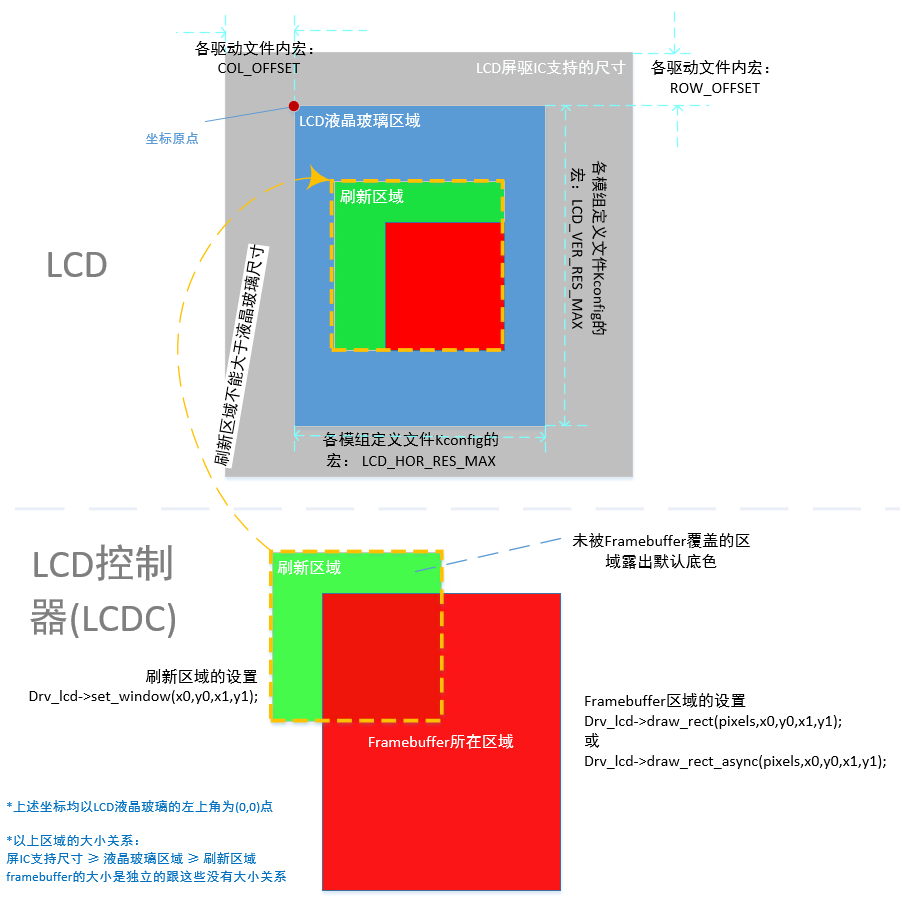
支持指定绘图区域, 且该区域可以跟给定的输出buffer区域任意交叉
支持帧同步和行同步
支持同步&异步(中断模式)送数接口
使用LCDC示例1
通过4SPI 1data接口驱动ST7789H2的屏幕
static LCDC_InitTypeDef lcdc_int_cfg =
{
    .lcd_itf = LCDC_INTF_SPI_DCX_1DATA,     //Choose 4SPI 1data interface
    .freq = 24000000,                       //SPI clock 24MHz
    .color_mode = LCDC_PIXEL_FORMAT_RGB565, //LCDC output color format RGB565
    .cfg = {
        .spi = {

            .dummy_clock = 1,                      //Dummy clock between cmd & data in read mode
            .syn_mode = HAL_LCDC_SYNC_VER,         //TE sychronization mode
            .vsyn_polarity = 0,                    //TE pin polarity
            .vsyn_delay_us = 1000,                 //Delay 1ms to send frame buffer right after received TE signal
            .hsyn_num = 0,                         //Hsyn num if syn_mode is HAL_LCDC_SYNC_VERHOR
        },
    },

};

LCDC_HandleTypeDef hlcdc_st7789h2;

__ROM_USED void LCDC1_IRQHandler(void)
{

    rt_interrupt_enter();

    HAL_LCDC_IRQHandler(lcdc);

    rt_interrupt_leave();
}


void HAL_LCDC_SendLayerDataCpltCbk(LCDC_HandleTypeDef *lcdc)
{
    /*Send layer data completed*/
}

/**
  * @brief  Power on the LCD.
  * @param  None
  * @retval None
  */
void ST7789H2_Init(LCDC_HandleTypeDef *hlcdc)
{
    uint8_t   parameter[14];

    //Initalize interface
    memcpy(&hlcdc->Init, &lcdc_int_cfg, sizeof(LCDC_InitTypeDef));
    HAL_LCDC_Init(hlcdc);

    //Generate a reset pulse to reset ST7789H2
    HAL_LCDC_ResetLCD(hlcdc, LCDC_RESX_NEG_PULSE, 10);

    /************* ST7789H2 initialize sequence start ************************/
    /*Sleep In Command */
    HAL_LCDC_WriteU8Reg(hlcdc, ST7789H2_SLEEP_IN, (uint8_t *)NULL, 0);
    /* Wait for 10ms */
    HAL_Delay(10);

    /* SW Reset Command */
    HAL_LCDC_WriteU8Reg(hlcdc, 0x01, (uint8_t *)NULL, 0);
    /* Wait for 200ms */
    HAL_Delay(200);

    /* Sleep Out Command */
    HAL_LCDC_WriteU8Reg(hlcdc, ST7789H2_SLEEP_OUT, (uint8_t *)NULL, 0);
    /* Wait for 120ms */
    HAL_Delay(120);

    ...
    /************* ST7789H2 initialize sequence end ************************/
}

/**
  * @brief  ST7789H2 read mode should slow down SPI clock to 4MHz
  * @param  enable: false - write spi mode |  true - read spi mode
  * @retval None
  */
void ST7789H2_ReadMode(LCDC_HandleTypeDef *hlcdc, bool enable)
{
    if (HAL_LCDC_IS_SPI_IF(lcdc_int_cfg.lcd_itf))
    {
        if (enable)
        {
            HAL_LCDC_SetFreq(hlcdc, 4000000); //SPI clock is 4MHz on Read mode
        }
        else
        {
            HAL_LCDC_SetFreq(hlcdc, lcdc_int_cfg.freq); //Restore normal frequency
        }

    }
}

/**
  * @brief  Reads the selected LCD Register.
  * @param  RegValue: Address of the register to read
  * @param  ReadSize: Number of bytes to read
  * @retval LCD Register Value.
  */
uint32_t ST7789H2_ReadData(LCDC_HandleTypeDef *hlcdc, uint16_t RegValue, uint8_t ReadSize)
{
    uint32_t rd_data = 0;

    //Entry read mode
    ST7789H2_ReadMode(hlcdc, true);

    HAL_LCDC_ReadU8Reg(hlcdc, RegValue, (uint8_t *)&rd_data, ReadSize);

    //Recovery to normal mode
    ST7789H2_ReadMode(hlcdc, false);

    return rd_data;
}

/**
 * @brief Set LCD & LCDC clip area
 * @param hlcdc LCD controller handle
 * @param Xpos0 - Clip area left coordinate, base on LCD top-left, same as below.
 * @param Ypos0 - Clip area top coordinate
 * @param Xpos1 - Clip area right coordinate
 * @param Ypos1 - Clip area bottom coordinate
 */
void ST7789H2_SetRegion(LCDC_HandleTypeDef *hlcdc, uint16_t Xpos0, uint16_t Ypos0, uint16_t Xpos1, uint16_t Ypos1)
{
    uint8_t   parameter[4];

    //Set LCDC clip area
    HAL_LCDC_SetROIArea(hlcdc, Xpos0, Ypos0, Xpos1, Ypos1);

    //Set LCD clip area
    parameter[0] = (Xpos0) >> 8;
    parameter[1] = (Xpos0) & 0xFF;
    parameter[2] = (Xpos1) >> 8;
    parameter[3] = (Xpos1) & 0xFF;
    HAL_LCDC_WriteU8Reg(hlcdc, ST7789H2_CASET, parameter, 4);

    parameter[0] = (Ypos0) >> 8;
    parameter[1] = (Ypos0) & 0xFF;
    parameter[2] = (Ypos1) >> 8;
    parameter[3] = (Ypos1) & 0xFF;
    HAL_LCDC_WriteU8Reg(hlcdc, ST7789H2_RASET, parameter, 4);
}


/**
 * @brief Send layer data to LCD
 * @param hlcdc LCD controller handle
 * @param RGBCode - Pointer to layer data
 * @param Xpos0 - Layer data left coordinate, base on LCD top-left, same as below.
 * @param Ypos0 - Layer data top coordinate
 * @param Xpos1 - Layer data right coordinate
 * @param Ypos1 - Layer data bottom coordinate
 */
void ST7789H2_WriteMultiplePixels(LCDC_HandleTypeDef *hlcdc, const uint8_t *RGBCode, uint16_t Xpos0, uint16_t Ypos0, uint16_t Xpos1, uint16_t Ypos1)
{
    uint32_t size;

    if ((Xpos0 > Xpos1) || (Ypos0 > Ypos1))
    {
        //Invalid coordinates
        return;
    }

    //Set default layer data
    HAL_LCDC_LayerSetData(hlcdc, HAL_LCDC_LAYER_DEFAULT, (uint8_t *)RGBCode, Xpos0, Ypos0, Xpos1, Ypos1);
    //Write datas to LCD register
    HAL_LCDC_SendLayerData2Reg_IT(hlcdc, 0x2c, 1);
}