
While Loop
HPSYS
Open serial debugging tool, connect to HCPU console serial port, connect measurement device to the module under test
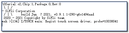
Reset, after successful startup the log shown below appears in HCPU console
Send command run_while_loop 192, instructing HCPU to execute while loop test at 192MHz frequency, measure average current C1 at this time. As shown in the HCPU While Loop test current diagram below, phase 1 is the current waveform in WFI mode when HCPU runs at 192MHz main frequency. After starting while loop execution, it enters phase 2, current rises and maintains until test completion. Phase 3 is the current waveform returning to WFI mode. Console displays HCPU frequency and while loop duration, as shown in the HCPU While Loop Log diagram.
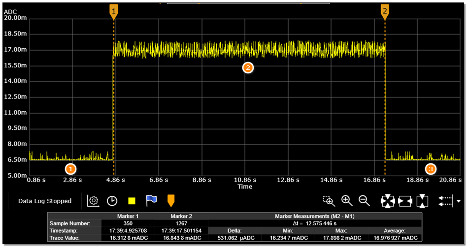
HCPU While Loop Test Current Diagram
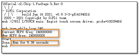
HCPU While Loop Log Diagram
Send command run_while_loop 168, instructing HCPU to execute while loop test at 168MHz, measure average current C2 at this time, thus obtaining current increment per MHz as C=(C1-C2)/(192-168)
Execute run_while_loop 144 and run_while_loop 120, measure average current at 144MHz and 120MHz, obtain incremental current at 144MHz as C=(C1-C2)/(144-120)
Execute run_while_loop 48 and run_while_loop 24, measure average current at 48MHz and 24MHz, obtain incremental current at 48MHz as C=(C1-C2)/(48-24)
Execute run_while_loop 24 and run_while_loop 12, measure average current at 24MHz and 12MHz, obtain incremental current at 24MHz as C=(C1-C2)/(24-12)