I2C MASTER例
源码路径:example/hal/i2c/master
支持的平台
例程可以运行在以下开发板.
sf32lb52-lcd系列
sf32lb58-lcd系列
sf32lb56-lcd系列
概述
本示例演示了如何使用芯片的I2C接口实现主从通信功能。代码实现了I2C主机模式(EXAMPLE_I2C_MASTER),在此模式下:
初始化I2C接口为主机模式
主动向地址为0x5A的从机发送4字节数据{0x11, 0x22, 0x33, 0x44}
从同一从机读取4字节响应数据
工作原理
在主机模式下,设备会循环执行以下操作:
向从机发送预设的4字节测试数据
延迟100毫秒
从从机读取4字节响应数据
延迟2秒后重复上述过程
例程的使用
以sf32lb52-lcd_n16r8开发板为例,运行本例程,查看串口输出。
硬件需求
运行该例程前,需要准备:
一块本例程支持的开发板
杜邦线若干
硬件连接
两块开发板I2C连接方式如下:
开发板 |
SDA管脚 |
SDA管脚名称 |
SCL管脚 |
SCL管脚名称 |
|---|---|---|---|---|
sf32lb52-lcd_n16r8 |
3 |
PA42 |
5 |
PA41 |
sf32lb56-lcd_n16r12n1 |
3 |
PA12 |
5 |
PA20 |
sf32lb58-lcd_n16r64n4 |
3 (CONN1) |
PB29 |
5 (CONN1) |
PB28 |
编译和烧录
切换到例程project目录,运行scons命令执行编译:
scons --board=sf32lb52-lcd_n16r8 -j8
运行build_sf32lb52-lcd_n16r8_hcpu\uart_download.bat,按提示选择端口即可进行下载:
build_sf32lb52-lcd_n16r8_hcpu\uart_download.bat

Uart Download

please input the serial port num:5
例程输出结果展示:
log输出:
SFBL
11-18 20:11:23:800 Serial:c2,Chip:4,Package:3,Rev:2 Reason:00000000
11-18 20:11:23:806 \ | /
11-18 20:11:23:807 - SiFli Corporation
11-18 20:11:23:808 / | \ build on Nov 18 2025, 2.4.0 build dd4cae55
11-18 20:11:23:809 2020 - 2022 Copyright by SiFli team
11-18 20:11:23:811 mount /dev sucess
11-18 20:11:23:812 [I/drv.rtc] PSCLR=0x80000100 DivAI=128 DivAF=0 B=256
11-18 20:11:23:813 [I/drv.rtc] RTC use LXT RTC_CR=00000001
11-18 20:11:23:814 [I/drv.rtc] Init RTC, wake = 0
11-18 20:11:23:817 [I/drv.audprc] init 00 ADC_PATH_CFG0 0x606
11-18 20:11:23:818 [I/drv.audprc] HAL_AUDPRC_Init res 0
11-18 20:11:23:819 [I/drv.audcodec] HAL_AUDCODEC_Init res 0
11-18 20:11:23:820 [32m[I/TOUCH] Regist touch screen driver, probe=1203bd11 [0m
11-18 20:11:23:823 call par CFG1(3313)
11-18 20:11:23:825 fc 9, xtal 2000, pll 2040
11-18 20:11:23:826 call par CFG1(3313)
11-18 20:11:23:827 fc 9, xtal 2000, pll 2040
11-18 20:11:23:828 Start I2C Slave Demo!
11-18 20:11:23:830 I2C Master Init Success!
11-18 20:11:23:834 === I2C Communication Test Start ===
11-18 20:11:23:835 Master sending 4 bytes to slave 0x5A: 0x11 0x22 0x33 0x44
11-18 20:11:23:837 Master transmit success!
11-18 20:11:23:838 Master reading 4 bytes from slave 0x5A
11-18 20:11:23:840 Master receive success, data: 0xAA 0xBB 0xCC 0xDD
11-18 20:11:23:842 === I2C Communication Test End ===
11-18 20:11:23:849 msh />
11-18 20:11:24:315 === I2C Communication Test Start ===
11-18 20:11:24:317 Master sending 4 bytes to slave 0x5A: 0x11 0x22 0x33 0x44
11-18 20:11:24:342 Master transmit success!
11-18 20:11:24:443 Master reading 4 bytes from slave 0x5A
11-18 20:11:24:445 Master receive success, data: 0xAA 0xBB 0xCC 0xDD
11-18 20:11:24:446 === I2C Communication Test End ===
11-18 20:11:24:944 === I2C Communication Test Start ===
11-18 20:11:24:944 Master sending 4 bytes to slave 0x5A: 0x11 0x22 0x33 0x44
11-18 20:11:24:947 Master transmit success!
11-18 20:11:25:042 Master reading 4 bytes from slave 0x5A
11-18 20:11:25:045 Master receive success, data: 0xAA 0xBB 0xCC 0xDD
11-18 20:11:25:046 === I2C Communication Test End ===
11-18 20:11:25:543 === I2C Communication Test Start ===
11-18 20:11:25:546 Master sending 4 bytes to slave 0x5A: 0x11 0x22 0x33 0x44
11-18 20:11:25:547 Master transmit success!
11-18 20:11:25:644 Master reading 4 bytes from slave 0x5A
11-18 20:11:25:646 Master receive success, data: 0xAA 0xBB 0xCC 0xDD
11-18 20:11:25:647 === I2C Communication Test End ===
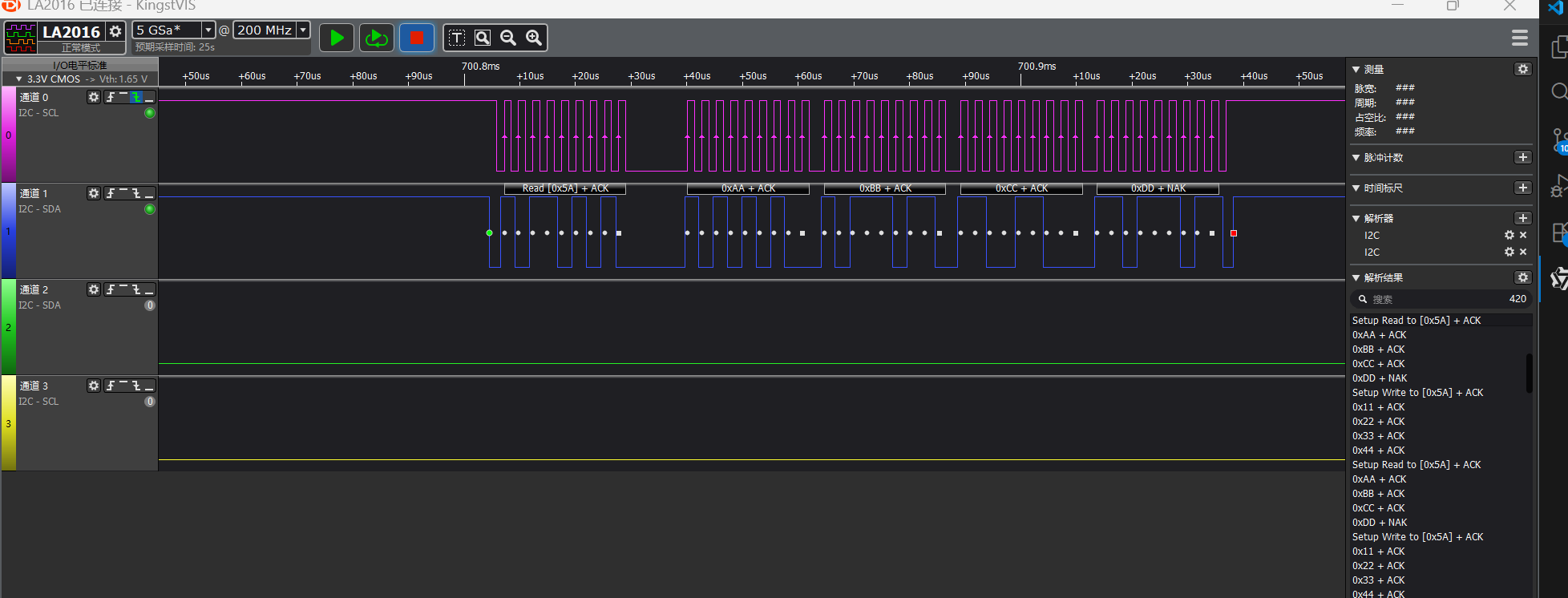
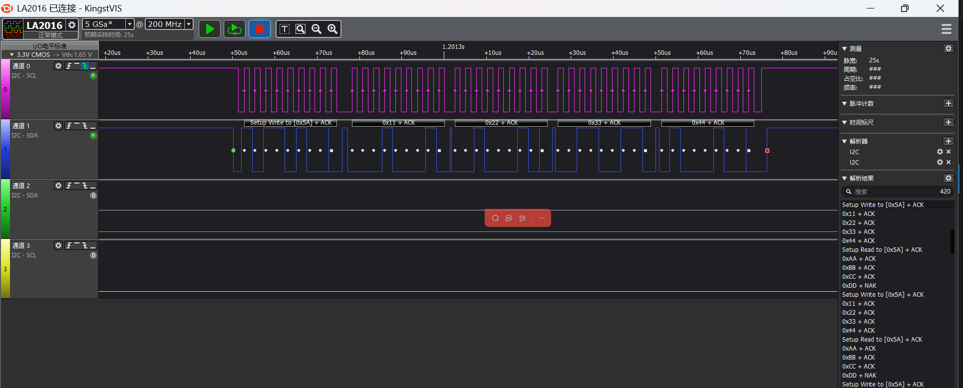
I2C读写波形
逻辑分析仪抓取部分波形
i2c master读的波形
i2c master写的波形
I2C参数修改
static I2C_HandleTypeDef hi2c;

#define SLAVE_ADDRESS 0x5A //slave address
uint8_t master_tx_data[] = {0x11, 0x22, 0x33, 0x44};//master send data
uint8_t master_rx_data[4];//master receive data

void I2C_Master_Init(void)
{
    HAL_StatusTypeDef ret;

    //pin nux
#ifdef SF32LB52X
    HAL_RCC_EnableModule(RCC_MOD_I2C2); // enable i2c2
    HAL_PIN_Set(PAD_PA41, I2C2_SCL, PIN_PULLUP, 1); // i2c io select
    HAL_PIN_Set(PAD_PA42, I2C2_SDA, PIN_PULLUP, 1);
#define SLAVE_I2C I2C2// i2c number of cpu
#elif defined(SF32LB58X)
    HAL_RCC_EnableModule(RCC_MOD_I2C6);  // enable i2c6
    HAL_PIN_Set(PAD_PB28, I2C6_SCL, PIN_PULLUP, 0); // i2c io select
    HAL_PIN_Set(PAD_PB29, I2C6_SDA, PIN_PULLUP, 0);
#define SLAVE_I2C I2C6// i2c number of cpu
#elif defined(SF32LB56X)
    HAL_RCC_EnableModule(RCC_MOD_I2C3); // enable i2c3
    HAL_PIN_Set(PAD_PA20, I2C3_SCL, PIN_PULLUP, 1); // i2c io select
    HAL_PIN_Set(PAD_PA12, I2C3_SDA, PIN_PULLUP, 1);
#define SLAVE_I2C I2C3// i2c number of cpu
#endif
    //i2c init
    hi2c.Instance = MASTER_I2C;
    hi2c.Mode = HAL_I2C_MODE_MASTER; // i2c master mode
    hi2c.Init.ClockSpeed = 400000;           // 400kHz
    hi2c.Init.AddressingMode = I2C_ADDRESSINGMODE_7BIT;
    hi2c.Init.GeneralCallMode = I2C_GENERALCALL_DISABLE;

    ret = HAL_I2C_Init(&hi2c);
    if (ret != HAL_OK) {
        rt_kprintf("I2C Master Init failed: %d\n", ret);
        return;
    }
    rt_kprintf("I2C Master Init Success!\n");
}
依据芯片类型区分开发板,在初始化函数中,针对特定芯片,配置与之对应的I2C引脚
例如通过
#elif defined(SF32LB52X)
芯片来进行一个判断使用的是哪个开发板通过
#define EXAMPLE_I2C I2C2
为该芯片使用的I2C控制器编号(比如I2C6、I2C3)通过
#define EXAMPLE_I2C_IRQ I2C6_IRQn
为该I2C控制器对应的中断号(用于中断模式)最后再通过HAL_PIN_Set()函数配置I2C的SCL和SDA引脚,并且需要设置为上拉模式
注意:
除55x芯片外,可以配置到任意带有PA*_I2C_UART功能的IO输出I2C的SDA,SCLK波形
HAL_PIN_Set 最后一个参数为hcpu/lcpu选择, 1:选择hcpu,0:选择lcpu
异常诊断
I2C无波形输出
对照芯片手册检查CPU的I2C是否选择正确
检查IO配置和连接是否正确