LCD Device
Introduction
LCD device is an rt_device with a simple LCD framework inside for registering different screen drivers. This chapter mainly introduces the usage and framework of LCD device, and how to register a new screen to this framework.
Internal Structure
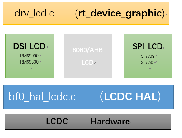
The LCD driver has 3 layers:
rt_device_graphic layer - Provides unified calling interface to upper layer
Supports multiple driver search functionality internally, convenient for compatibility with multiple screens (determined by comparing registered ID and ReadID function return value)
Contains 3 framebuffer mechanisms internally, allowing rendering and screen refresh to proceed simultaneously, supporting compression.
Specific driver logic layer
Specific interface, frequency, TE and other configurations for each screen driver, as well as initialization code, screen refresh commands, sleep, and power on/off instructions
Physical interface abstraction layer for screens
Provides unified operation functions for most interfaces. See LCDC for details
Note
The SDK implements 2 rt_device_graphic instances with rt_device names:
lcd(drv_lcd.c)
Normal physical LCD screen
ram_lcd(drv_ram_lcd.c)
Writes output to SRAM (when enabled, will allocate an LCD buffer from system heap memory)
ram_lcd usage is the same as normal screens (fixed screen size)
Example of Upper Layer Using LCD Device
Draw a 100*100 RGB565 format red area in the center of the screen. Each refresh deepens the red color slightly, cycling after 32 times.
#define RGB565_FB_WIDTH  100
#define RGB565_FB_HEIGHT  100
static uint16_t rgb565_frambuffer[RGB565_FB_WIDTH * RGB565_FB_HEIGHT];

static struct rt_semaphore lcd_sema;

static rt_err_t lcd_flush_done(rt_device_t dev, void *buffer)
{
    rt_sem_release(&lcd_sema);
    return RT_EOK;
}

void lcd_flush_task(void *parameter)
{

    rt_err_t ret;
    uint8_t color = 0;
    struct rt_device_graphic_info info;
    uint16_t framebuffer_color_format = RTGRAPHIC_PIXEL_FORMAT_RGB565;


    /* LCD Device Init */
    rt_device_t lcd_device = rt_device_find("lcd");
    RT_ASSERT(lcd_device != RT_NULL);
    rt_device_set_tx_complete(lcd_device, lcd_flush_done);
    if (rt_device_open(lcd_device, RT_DEVICE_OFLAG_RDWR) == RT_EOK)
    {
        if (rt_device_control(lcd_device, RTGRAPHIC_CTRL_GET_INFO, &info) == RT_EOK)
        {
            rt_kprintf("Lcd info w:%d, h%d, bits_per_pixel %d\r\n", info.width, info.height, info.bits_per_pixel);
        }
    }

    rt_device_control(lcd_device, RTGRAPHIC_CTRL_SET_BUF_FORMAT, &framebuffer_color_format);

    rt_sem_init(&lcd_sema, "lv_lcd", 1, RT_IPC_FLAG_FIFO);


    while (1)
    {
        rt_err_t err;
        int32_t dx, dy;

        /*Draw framebuffer at center of screen*/
        dx = (info.width - RGB565_FB_WIDTH) / 2;
        dy = (info.height - RGB565_FB_HEIGHT) / 2;

         /* Fill RGB565 framebuffer with red color*/
        color = (color + 1) % 0x1F;
        for(uint32_t i = 0; i < RGB565_FB_HEIGHT; i++)
            for(uint32_t j = 0; j < RGB565_FB_WIDTH; j++)
                {
                    rgb565_frambuffer[(i * RGB565_FB_WIDTH) + j] = ((uint16_t )color) << 11;
                }

        //Wait lcd_flush_done to release lcd_sema
        err = rt_sem_take(&lcd_sema, rt_tick_from_millisecond(1000));
        RT_ASSERT(RT_EOK == err);

		/*
			Set the valid area for drawing operations, all coordinates below have their origin at the top-left corner of the screen
		*/
        rt_graphix_ops(lcd_device)->set_window(dx, dy, dx + RGB565_FB_WIDTH - 1, dy + RGB565_FB_HEIGHT - 1);

		/*
			Draw a buffer to the LCD device, asynchronous function, calls lcd_flush_done when complete

			About the {x0,y0,x1,y1} area:
			   1. This area represents the region the entire buffer occupies on the screen, not for clipping the buffer
			   2. If only updating part of the buffer, use in conjunction with set_window function
        */
        rt_graphix_ops(lcd_device)->draw_rect_async((const char *)&rgb565_frambuffer, dx, dy, dx + RGB565_FB_WIDTH - 1, dy + RGB565_FB_HEIGHT - 1);

    }
}
Process for Adding a New Screen
1. Select the corresponding board project under example\rt_driver
This project contains a simple example of drawing rectangular areas (see previous “rt_device_graphic layer interface usage example”)
If choosing to use the watch_demo project, you need to disable the tp thread before tuning the screen to prevent TP failure from blocking the UI screen refresh thread (disable method: in
drv_touch.ctouch_openfunction, remove rt_thread_startup(touch_thread); )
2. Add new driver to compilation project
Add new screen code to directory customer\peripherals
You can copy code from other existing drivers, then change the name, ID, and corresponding commands (most are the same and don’t need changes) to your own
Note to modify the depend macro in the internal Kconfig file
Screen driver registration macro explanation:
LCD_DRIVER_EXPORT(
    rm69090,   //Screen driver name, string
    RM69090_ID,  //Screen driver ID, used to compare with RM69090_ReadID return value
    &lcdc_int_cfg, //Screen driver initialization configuration (including interface, frequency, output color format, etc.)
    &RM69090_drv,  //Screen driver external API interface implementation
    RM69090_LCD_PIXEL_WIDTH,  // IC's maximum horizontal resolution (note: not glass resolution)
    RM69090_LCD_PIXEL_HEIGHT, // IC's maximum vertical resolution (note: not glass resolution)
    2                //Pixel alignment during refresh (write 1 if not needed)
    );
Note
Glass resolution is fixed in the LCD_DRIVER_EXPORT macro definition, see macros LCD_HOR_RES_MAX and LCD_VER_RES_MAX
In customer\peripherals\Kconfig, add a hidden option for the newly added driver, for example:
config LCD_USING_RM69090
    bool
    default n
Add screen module switch in board-level configuration. The module switch should select the previously added hidden switch and the interface switch used (interface switch is used to modify pinmux), for example, in customer\boards\ec-lb551XXX\Kconfig, add module switch:
config LCD_USING_ED_LB55SPI17801_QADSPI_LB551
    bool "1.78 rect QAD-SPI LCD(ED-LB55SPI17801)"
    select TSC_USING_FT3168 if BSP_USING_TOUCHD
    select LCD_USING_RM69090
    select BSP_LCDC_USING_QADSPI
    if LCD_USING_ED_LB55SPI17801_QADSPI_LB551
        config LCD_RM69090_VSYNC_ENABLE
            bool "Enable LCD VSYNC (TE signal)"
            def_bool n
    endif
Note
Touch controller addition process is similar to screen, and should be selected together in this module switch
Still in the above file, define resolution and DPI values for the newly added screen (Note: this is the module glass resolution, not the maximum resolution the screen IC can support)
config LCD_HOR_RES_MAX
    int
    default 454 if LCD_USING_ED_LB55SPI17201_QADSPI_LB551
    default 400 if LCD_USING_ED_LB55_77903_QADSPI_LB551
    default 240 if LCD_USING_ED_LB55_387A_JDI_LB551
    default 368 if LCD_USING_ED_LB55SPI17801_QADSPI_LB551    <-------- Newly added line

config LCD_VER_RES_MAX
    int
    default 454 if LCD_USING_ED_LB55SPI17201_QADSPI_LB551
    default 400 if LCD_USING_ED_LB55_77903_QADSPI_LB551
    default 240 if LCD_USING_ED_LB55_387A_JDI_LB551
    default 448 if LCD_USING_ED_LB55SPI17801_QADSPI_LB551    <-------- Newly added line

config LCD_DPI
    int
    default 315 if LCD_USING_ED_LB55SPI17201_QADSPI_LB551
    default 315 if LCD_USING_ED_LB55_77903_QADSPI_LB551
    default 315 if LCD_USING_ED_LB55_387A_JDI_LB551
    default 315 if LCD_USING_ED_LB55SPI17801_QADSPI_LB551    <-------- Newly added line
If using scons compilation, enter the project menuconfig selection menu, then select the newly added screen module, finally generating .config and rtconfig.h
If using Keil compilation, you can also directly add source code (but still recommend the same method as scons compilation, so it will be automatically included when regenerating Keil project next time)
3. Check pinmux for pins used by new LCD and reset pin
As mentioned earlier, when configuring modules, an interface macro will be selected. The SDK internally handles pin mux processing for different LCDC interface macros
Since reset pin is controlled by independent GPIO, need to confirm if the pin controlled by
BPS_LCD_Resetfunction is correct
4. Modify interface, frequency, and output color format of new screen
See example below, modify the
init_cfgstructure inLCD_DRIVER_EXPORTmacro (output frequency may differ from configured value, please use actual output as reference, because HAL layer implementation output frequency = HCLK/divider, HCLK can be viewed by entering “sysinfo” in console, divider is an integer from 2~255)It’s recommended to disable TE during initial debugging to prevent LCDC from not sending data due to waiting for TE signal (our TE signal is handled automatically by LCDC, no software involvement needed)
Note
Our TE signal is handled automatically by LCDC, no software involvement needed, so there’s no TE software interrupt. As long as TE pin mux and polarity are configured correctly, after starting LCDC data transmission (HAL_LCDC_SendLayerData2Reg_IT), LCDC will start sending data when it receives TE pulse
5. Using Any GPIO as TE Signal (Optional)
In most cases, as long as the corresponding pin is defined as TE function, LCDC can automatically handle TE signal. However, in some special cases where TE signal cannot come from the expected path, it needs to be changed to ordinary GPIO implementation. At this time, software GPIO interrupt method can be used:
Enable TE and set TE delay according to normal configuration
Define macro “
LCD_USE_GPIO_TE” as an ordinary GPIO, which will actively create a TE signal (flip TE polarity) on interrupt rising edge to trigger LCDC data transmission
Note
Since normal TE path is not working, the first step setting cannot work, only the second step artificial signal creation can trigger data transmission to achieve normal TE processing
6. Modify initialization code of new screen driver
Generally, first initialize LCDC, configure interface, frequency, etc. Call API - HAL_LCDC_Init.
Then reset LCD through
BPS_LCD_Resetfunction implemented in drv_io.c to control GPIO reset screen.Then the initialization code provided by screen manufacturer
7. Modify read id function
drv_lcd.cwill use this function’s return value to compare with ID registered inLCD_DRIVER_EXPORT. Only when they match will the driver be considered usable and called.
8. QAD-SPI LCD Extended Command Modification
QAD-SPI LCD generally extends standard 8bit commands to 32bit, need to modify extension method. Can refer to rm69330.c, generally these functions need modification: RM69330_WriteMultiplePixels, RM69330_WriteReg, RM69330_ReadData.
Customer New Screen Driver Code Example (Partial)
The following example code shows how RM69330 registers to drv_lcd.c (rt_device_graphic layer) and interface configuration, function callbacks, etc. Please refer to SDK code for specific implementation of each function, not detailed here.
//RM69330 chip IDs
#define RM69330_ID                  0x8000


//RM69330 resolution
#define  RM69330_LCD_PIXEL_WIDTH    (454)
#define  RM69330_LCD_PIXEL_HEIGHT   (454)

//Interface, Frequency, Output color format, TE
static LCDC_InitTypeDef lcdc_int_cfg_qspi =
{
    .lcd_itf = LCDC_INTF_SPI_DCX_4DATA, //QAD-SPI mode
    .freq = 48000000,
    .color_mode = LCDC_PIXEL_FORMAT_RGB565,

    .cfg = {
        .spi = {
            .dummy_clock = 0, //0: QAD-SPI/SPI3   1:SPI4
            .syn_mode = HAL_LCDC_SYNC_VER,
            .vsyn_polarity = 0,
            .vsyn_delay_us = 1000,
            .hsyn_num = 0,
        },
    },

};

//Function callbacks
static const LCD_DrvOpsDef RM69330_drv =
{
    RM69330_Init,
    RM69330_ReadID,
    RM69330_DisplayOn,
    RM69330_DisplayOff,

    RM69330_SetRegion,
    RM69330_WritePixel,
    RM69330_WriteMultiplePixels,

    RM69330_ReadPixel,

    RM69330_SetColorMode,
    RM69330_SetBrightness
};


//Register to drv_lcd.c
LCD_DRIVER_EXPORT(rm69330, RM69330_ID, &lcdc_int_cfg_qspi,
    &RM69330_drv,
    RM69330_LCD_PIXEL_WIDTH,
    RM69330_LCD_PIXEL_HEIGHT,2);
Note
As mentioned earlier, drv_lcd.c during initialization will compare RM69330_ID registered in LCD_DRIVER_EXPORT and ID returned by RM69330_ReadID, only when they match will it be called.
Supporting Multiple Screen Modules Simultaneously
Assuming compatibility with 2 modules:
Module 1: LB55SPI17801 (screen IC is RM69090, touch IC is FT3168),
Module 2: LB55BILI8688E (screen IC is ILI8688E, touch IC is CST918),
Same as adding screens before, just add an item to the project’s corresponding Kconfig file that simultaneously selects both modules’ screen drivers and touch drivers (note: screen driver’s ReadID function must be able to distinguish between the 2 ICs, similarly touch probe function must also be able to distinguish different ICs).
Kconfig file example:
config LCD_USING_ED_LB55SPI17801_LB55BILI8688E_QADSPI_LB551
    bool "1.78 rect QAD-SPI LCD(ED-LB55SPI17801 and ED-LB55BILI8688E)"
    select TSC_USING_FT3168 if BSP_USING_TOUCHD
    select TSC_USING_CST918 if BSP_USING_TOUCHD
    select LCD_USING_RM69090
    select LCD_USING_ILI8688E
    select BSP_LCDC_USING_QADSPI
    if LCD_USING_ED_LB55SPI17801_LB55BILI8688E_QADSPI_LB551
        config LCD_RM69090_VSYNC_ENABLE
            bool
            def_bool n
        config LCD_ILI8688E_VSYNC_ENABLE
            bool
            def_bool y
    endif
Note
Other screen resolution configurations and DPI configurations can share the LCD_USING_ED_LB55SPI17801_LB55BILI8688E_QADSPI_LB551 macro for setting, since these parameters should be the same for compatibility
DSI Screen Debugging
It’s recommended to debug low-speed mode first because low-speed can bypass hardware-caused issues and is easy to analyze with oscilloscope. After low-speed mode is working, read ID - reading ID can check if screen power-on is normal. After low-speed mode read ID and screen refresh are normal, then switch to high-speed mode for screen refresh.
DSI Low-Speed Mode Operation Flow
Reduce LCDC data transmission speed
Need to reduce system clock to 48M, in
drv_io.c, change HAL_RCC_HCPU_ClockSelect(RCC_CLK_MOD_SYS, XXX); XXX is the system clock frequency, change to RCC_SYSCLK_HXT48 (crystal clock 48MHz)Change all commands to LP mode (low-speed mode) transmission, and enable LCD acknowledge for easy waveform analysis with logic analyzer or oscilloscope (configure in the
LCDC_InitTypeDefstructure mentioned earlier, as follows:)
    .LPCmd = {
    .LPGenShortWriteNoP    = DSI_LP_GSW0P_ENABLE,
    .LPGenShortWriteOneP   = DSI_LP_GSW1P_ENABLE,
    .LPGenShortWriteTwoP   = DSI_LP_GSW2P_ENABLE,
    .LPGenShortReadNoP     = DSI_LP_GSR0P_ENABLE,
    .LPGenShortReadOneP    = DSI_LP_GSR1P_ENABLE,
    .LPGenShortReadTwoP    = DSI_LP_GSR2P_ENABLE,
    .LPGenLongWrite        = DSI_LP_GLW_ENABLE,
    .LPDcsShortWriteNoP    = DSI_LP_DSW0P_ENABLE,
    .LPDcsShortWriteOneP   = DSI_LP_DSW1P_ENABLE,
    .LPDcsShortReadNoP     = DSI_LP_DSR0P_ENABLE,
    .LPDcsLongWrite        = DSI_LP_DLW_ENABLE,      //DSI_LP_DLW_DISABLE,      ENABLE - LP mode, DISABLE - high speed mode
    .LPMaxReadPacket       = DSI_LP_MRDP_ENABLE,
    .AcknowledgeRequest    = DSI_ACKNOWLEDGE_ENABLE, //Enable LCD error reports
},
Note
After setting _init->cfg.dsi.LPCmd.LPDcsLongWrite_ to `DSI_LP_DLW_ENABLE`, _HAL_LCDC_Init_ will automatically reduce DBI transmission frequency to minimum (48 * 16 / 126 = ~6Mbps, where 48 is system clock, 16 is DBI bandwidth, 126 is maximum division factor)Adjust DSI LP mode frequency to screen-supported range (generally 6~20Mbps), with following configuration LP frequency = 480 / 8 / 4 = 15Mbps (where 480 is freq, 8 is fixed value, 4 is TXEscapeCkdiv)
static LCDC_InitTypeDef lcdc_int_cfg_dsi =
{
    .lcd_itf = LCDC_INTF_DSI,
    .freq = DSI_FREQ_480MHZ,
    .color_mode = LCDC_PIXEL_FORMAT_RGB888,

    .cfg = {

        .dsi = {

            .Init = {
                .AutomaticClockLaneControl = DSI_AUTO_CLK_LANE_CTRL_ENABLE,
                .NumberOfLanes = RM69090_DSI_DATALANES,
                .TXEscapeCkdiv = 0x4,
            },

            ...
            }
            ...
        }
        ...
}
Extend screen refresh timeout in drv_lcd layer, otherwise default 500ms easily times out at low speed. Adjust macro
MAX_LCD_DRAW_TIMEvalue.Enable log in
bf0_hal_dsi.c(need to override HAL_DBG_printf), can check communication process errors through log#define DSI_LOG_D(...) HAL_DBG_printf(__VA_ARGS__) #define DSI_LOG_E(...) HAL_DBG_printf(__VA_ARGS__)
If conditions permit, use logic analyzer or oscilloscope to capture waveforms on P,N pins of DATALANE0, parse whether commands, color formats, etc. are expected data
Note
When reading ID, check if screen has ack after bus turnaround. If not, power-on or reset may be abnormal
DSI High-Speed Mode Configuration
After low-speed mode can read ID and refresh expected colors, can switch to high-speed mode, generally it will work.
High-speed mode needs to change AcknowledgeRequest to disable, otherwise it easily causes data transmission fifo overflow
Also note that some screens have different maximum frequencies for different color formats.
Configure in the LCDC_InitTypeDef structure mentioned earlier:
    .LPCmd = {
    ...
    .LPDcsLongWrite        = DSI_LP_DLW_DISABLE, //High-speed mode mainly changes long packets to high-speed mode here
    ...
    .AcknowledgeRequest    = DSI_ACKNOWLEDGE_DISABLE, //Need to disable Ack packets in high-speed mode
}
DSI Color and TE Function Configuration
DSI color format reference DSI
DSI TE function DSI TE has 2 optional paths: through DSI link or through LCDC_TE function pin If using LCDC_TE pin, need to simultaneously specify physical pin pinmux as LCDC_TE function (can be LCDCx_SPI_TE/LCDCx_8080_TE)
    static LCDC_InitTypeDef lcdc_int_cfg_dsi =
    {
        .lcd_itf = LCDC_INTF_DSI,
        .freq = DSI_FREQ_480MHZ,
        .color_mode = LCDC_PIXEL_FORMAT_RGB888,

        .cfg = {
            .dsi = {
                    ...
                .CmdCfg = {
                    ...
                    .TearingEffectSource   = DSI_TE_EXTERNAL, <<<----  DSI_TE_EXTERNAL means using LCDC_TE pin, DSI_TE_DSILINK means using DSI link
Note
On 55x series chips, DSI using LCDC_TE function pin is not supported. Please refer to the “Using Any GPIO as TE Signal” section above.