PWM Example
Source code path: example/hal/pwm
Supported Platforms
The example can run on the following development boards.
sf32lb52-nano
sf32lb52-lcd series
sf32lb56-lcd series
sf32lb58-lcd series
Overview
Contains examples of GPtimer outputting PWM through IO ports
Contains examples of using Atimer to output complementary PWM through IO
Example Usage
Compilation and Programming
Switch to the example project directory and run the scons command to compile (board=board type):
scons --board=sf32lb52-lcd_n16r8 -j8
build_sf32lb52-lcd_n16r8_hcpu\uart_download.bat, select the port as prompted to download:
build_sf32lb52-lcd_n16r8_hcpu\uart_download.bat

Uart Download

please input the serial port num:5
For detailed steps on compilation and downloading, please refer to the relevant introduction in Getting Started Guide.
GPtimer Output PWM
Example Output Results Display:
Log output:
SFBL
Start gtimer pwm demo!
GPT_clock 24000000,psc 2, Period 60000,Pulse 12000
gtimer pwm demo end!
msh />
PA09 outputs PWM waveform (default 200Hz, 20% duty cycle)

PWM Parameter Modification
IO output modification
Physical position refers to the actual pin position on the board’s header
Board Name |
PWM |
CHX |
Pin (Physical Position) |
|---|---|---|---|
sf32lb52-nano |
GPTIM2 |
CH1 |
PA09 (manually routed from back side) |
sf32lb52-lcd |
GPTIM2 |
CH1 |
PA09 (37) |
sf32lb56-lcd |
GPTIM2 |
CH1 |
PA36 (40) |
sf32lb58-lcd |
GPTIM1 |
CH2 |
PA51 (CONN2 28) |
    #define PAD_PA_09 PAD_PA09 /* 52 series default PA09 output (physical position 37) */
    HAL_PIN_Set(PAD_PA_09, cfg->pad_func, PIN_PULLUP, 1);/*Configure PA09 as GPTIM2_CH1 function*/


    #define PAD_PA_51 PAD_PA51/* 58 series default PA51 output (physical position CONN2 28) */
    HAL_PIN_Set(PAD_PA_51, cfg->pad_func, PIN_PULLUP, 1);/*Configure PA51 as GPTIM1_CH2 function*/
Note:
Except for 55x chips, can be configured to any IO with PA_TIM function to output PWM waveform (to query pin multiplexing table, you can search for the corresponding board type pin multiplexing in the project path files such as: bf0_pin_const.c)
The last parameter of HAL_PIN_Set is for hcpu/lcpu selection, 1: select hcpu, 0: select lcpu
PWM period period, pulse width pulse modification
#if defined(BSP_USING_BOARD_EM_LB525XXX)
    T_haltest_pwm_cfg testcfg[] =
{
    {hwp_gptim2, CORE_ID_HCPU, GPTIM2_CH1, GPT_CHANNEL_1, 5000000, 1000000, 0},
};  //period:0.5s  pulse:0.25s
#elif defined BSP_USING_BOARD_EM_LB587XXX
    T_haltest_pwm_cfg testcfg[] =
{
    {hwp_gptim1, CORE_ID_HCPU, GPTIM1_CH2, GPT_CHANNEL_2, 5000000, 1000000, 0},
};  //period:0.5s  pulse:0.25s
#endif
Parameter: 5000000 unit is ns, corresponding period is 1/0.005s=200Hz
Parameter: 1000000 unit is ns, represents the pulse width of PWM output 1 in one period, cannot be greater than the above parameter,
1000000/5000000=1/5=20% duty cycle
ATtimer Output Complementary PWM
Example Output Results Display:
Log output:
Start atimer pwm demo!
ATIM1_Init
frequency:50000,percentage1:50,percentage2:30
channel1 atim1 plck freq:120000000,PWM_PERIOD:20000,PWM_PULSE:10000
atim1 GPT_clock:120,period:2400,psc:1
atim1 pulse:1200
channel2 atim1 plck freq:120000000,PWM_PERIOD:20000,PWM_PULSE:6000
atim1 GPT_clock:120,period:2400,psc:1
frequency:10000,percentage1:5,percentage2:90
channel1 atim1 plck freq:120000000,PWM_PERIOD:100000,PWM_PULSE:5000
atim1 GPT_clock:120,period:12000,psc:1
atim1 pulse:600
channel2 atim1 plck freq:120000000,PWM_PERIOD:100000,PWM_PULSE:90000
atim1 GPT_clock:120,period:12000,psc:1
frequency:1000,percentage1:95,percentage2:5
channel1 atim1 plck freq:120000000,PWM_PERIOD:1000000,PWM_PULSE:950000
atim1 GPT_clock:120,period:120000,psc:1
atim1 pulse:114000
channel2 atim1 plck freq:120000000,PWM_PERIOD:1000000,PWM_PULSE:50000
atim1 GPT_clock:120,period:120000,psc:1
ATIM1_Stop!
atimer pwm demo end!
Physical position refers to the pin position corresponding to the board’s header
Board Name |
PWM |
Output Channel1 |
Output Channel2 |
|---|---|---|---|
525 |
ATIM1 |
PAD_PA00 (physical position 32), PAD_PA02 (physical position 36) |
PAD_PA03 (physical position 40), PAD_PA03 (physical position 38) |
587 |
ATIM2 |
PAD_PA84 (conn2 21), PAD_PA86 (conn2 24) |
PAD_PA90 (conn2 27), PAD_PA91 (conn2 26) |
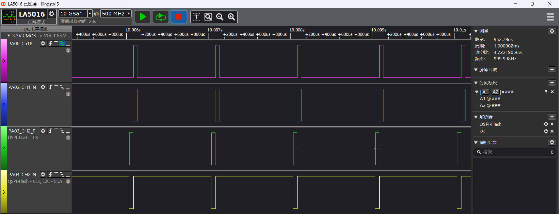
52 series: PA00, PA02 output Channel1 complementary PWM waveform, PA03, PA04 output Channel2 complementary PWM waveform:
587 series: PA84, PA86 output Channel1 complementary PWM waveform, PA90, PA91 output Channel2 complementary PWM waveform:
PWM Parameter Modification
ATIM modification: 52 series selects ATIM1, 587 selects ATIM2
    #if defined(BSP_USING_BOARD_EM_LB525XXX)
    atim_Handle.Instance = (GPT_TypeDef *)hwp_atim1;

    #elif defined (BSP_USING_BOARD_EM_LB587XXX)
    atim_Handle.Instance = (GPT_TypeDef *)hwp_atim2;
    #endif
IO output modification Except for 55x chips, can be configured to any IO with PA_TIM function to output PWM waveform

#if defined(BSP_USING_BOARD_EM_LB525XXX)
	HAL_PIN_Set(PAD_PA00, ATIM1_CH1,  PIN_PULLUP, 1);
    HAL_PIN_Set(PAD_PA02, ATIM1_CH1N, PIN_PULLUP, 1);
    HAL_PIN_Set(PAD_PA03, ATIM1_CH2,  PIN_PULLUP, 1);
    HAL_PIN_Set(PAD_PA04, ATIM1_CH2N, PIN_PULLUP, 1);

#elif defined(BSP_USING_BOARD_EM_LB587XXX)
    HAL_PIN_Set(PAD_PA84, ATIM2_CH1,  PIN_PULLUP, 1);
    HAL_PIN_Set(PAD_PA86, ATIM2_CH1N, PIN_PULLUP, 1);
    HAL_PIN_Set(PAD_PA90, ATIM2_CH2,  PIN_PULLUP, 1);
    HAL_PIN_Set(PAD_PA91, ATIM2_CH2N, PIN_PULLUP, 1);
#endif
PWM period period, pulse width pulse modification, use delay function to maintain waveform for 2s
    freq = 50000;   /* 50000 is PWM frequency (unit hz) minimum 1Hz, maximum 200000Hz */
    percentage1=50; /* 50 is Channel 1 duty cycle 50% (unit %) minimum 0(0%), maximum 100(100%)*/
    percentage2=50; /* 50 is Channel 2 duty cycle 50% (unit %) minimum 0(0%), maximum 100(100%)*/
    HAL_Delay(2000)
    freq = 10000;   /* 10000 is frequence of pwm(10000hz)*/
    percentage1 = 5; /* 5 is the duty cycle of Channel 1(5%)*/
    percentage2 = 90; /* 90 is the duty cycle of Channel 2(90%)*/
    HAL_Delay(2000)
    freq = 1000; //hz
    percentage1 = 95;
    percentage2 = 5;
    HAL_Delay(2000)
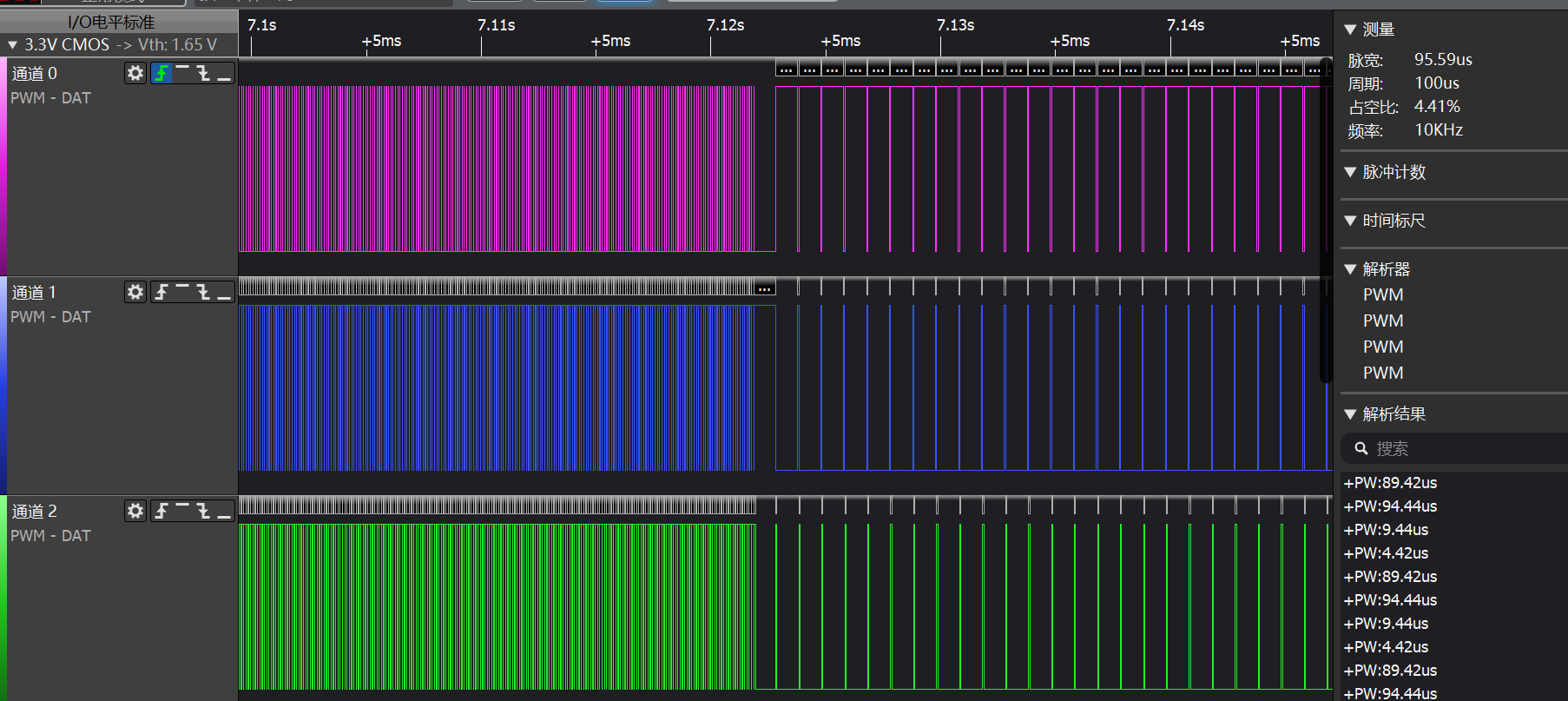
Waveform change diagrams between different parameters

Exception Diagnosis
If the expected logs and PWM waveform output do not appear, troubleshooting can be performed from the following aspects:
Whether hardware connection is normal
Whether pin configuration is correct
Whether the pin corresponds to the correct channel
Reference Documents
Update Log
Version |
Date |
Release Notes |
|---|---|---|
0.0.1 |
10/2024 |
Initial version |
0.0.2 |
12/2024 |
2.0 |