I2C MASTER Example
Source code path: example/hal/i2c/master
Supported Platforms
The example can run on the following development boards:
sf32lb52-lcd series
sf32lb58-lcd series
sf32lb56-lcd series
Overview
This example demonstrates how to use the chip’s I2C interface to implement master-slave communication functionality. The code implements I2C Master Mode (EXAMPLE_I2C_MASTER), in this mode:
Initialize I2C interface in master mode
Actively send 4-byte data {0x11, 0x22, 0x33, 0x44} to the slave at address 0x5A
Read 4-byte response data from the same slave
Working Principle
In master mode, the device cyclically performs the following operations:
Send preset 4-byte test data to the slave
Delay 100 milliseconds
Read 4-byte response data from the slave
Repeat the above process after 2 seconds
Example Usage
Using sf32lb52-lcd_n16r8 development board as an example, run this example and check the serial output.
Hardware Requirements
Before running this example, you need to prepare:
One development board supported by this example
Several Dupont wires
Hardware Connection
The I2C connection method for two development boards is as follows:
Development Board |
SDA Pin |
SDA Pin Name |
SCL Pin |
SCL Pin Name |
|---|---|---|---|---|
sf32lb52-lcd_n16r8 |
3 |
PA42 |
5 |
PA41 |
sf32lb56-lcd_n16r12n1 |
3 |
PA12 |
5 |
PA20 |
sf32lb58-lcd_n16r64n4 |
3 (CONN1) |
PB29 |
5 (CONN1) |
PB28 |
Compilation and Programming
Switch to the example project directory and run the scons command to compile:
scons --board=sf32lb52-lcd_n16r8 -j8
Run build_sf32lb52-lcd_n16r8_hcpu\uart_download.bat, and follow the prompts to select the port for downloading:
build_sf32lb52-lcd_n16r8_hcpu\uart_download.bat

Uart Download

please input the serial port num:5
Example Output Results:
Log output:
SFBL
11-18 20:11:23:800 Serial:c2,Chip:4,Package:3,Rev:2 Reason:00000000
11-18 20:11:23:806 \ | /
11-18 20:11:23:807 - SiFli Corporation
11-18 20:11:23:808 / | \ build on Nov 18 2025, 2.4.0 build dd4cae55
11-18 20:11:23:809 2020 - 2022 Copyright by SiFli team
11-18 20:11:23:811 mount /dev sucess
11-18 20:11:23:812 [I/drv.rtc] PSCLR=0x80000100 DivAI=128 DivAF=0 B=256
11-18 20:11:23:813 [I/drv.rtc] RTC use LXT RTC_CR=00000001
11-18 20:11:23:814 [I/drv.rtc] Init RTC, wake = 0
11-18 20:11:23:817 [I/drv.audprc] init 00 ADC_PATH_CFG0 0x606
11-18 20:11:23:818 [I/drv.audprc] HAL_AUDPRC_Init res 0
11-18 20:11:23:819 [I/drv.audcodec] HAL_AUDCODEC_Init res 0
11-18 20:11:23:820 [32m[I/TOUCH] Regist touch screen driver, probe=1203bd11 [0m
11-18 20:11:23:823 call par CFG1(3313)
11-18 20:11:23:825 fc 9, xtal 2000, pll 2040
11-18 20:11:23:826 call par CFG1(3313)
11-18 20:11:23:827 fc 9, xtal 2000, pll 2040
11-18 20:11:23:828 Start I2C Slave Demo!
11-18 20:11:23:830 I2C Master Init Success!
11-18 20:11:23:834 === I2C Communication Test Start ===
11-18 20:11:23:835 Master sending 4 bytes to slave 0x5A: 0x11 0x22 0x33 0x44
11-18 20:11:23:837 Master transmit success!
11-18 20:11:23:838 Master reading 4 bytes from slave 0x5A
11-18 20:11:23:840 Master receive success, data: 0xAA 0xBB 0xCC 0xDD
11-18 20:11:23:842 === I2C Communication Test End ===
11-18 20:11:23:849 msh />
11-18 20:11:24:315 === I2C Communication Test Start ===
11-18 20:11:24:317 Master sending 4 bytes to slave 0x5A: 0x11 0x22 0x33 0x44
11-18 20:11:24:342 Master transmit success!
11-18 20:11:24:443 Master reading 4 bytes from slave 0x5A
11-18 20:11:24:445 Master receive success, data: 0xAA 0xBB 0xCC 0xDD
11-18 20:11:24:446 === I2C Communication Test End ===
11-18 20:11:24:944 === I2C Communication Test Start ===
11-18 20:11:24:944 Master sending 4 bytes to slave 0x5A: 0x11 0x22 0x33 0x44
11-18 20:11:24:947 Master transmit success!
11-18 20:11:25:042 Master reading 4 bytes from slave 0x5A
11-18 20:11:25:045 Master receive success, data: 0xAA 0xBB 0xCC 0xDD
11-18 20:11:25:046 === I2C Communication Test End ===
11-18 20:11:25:543 === I2C Communication Test Start ===
11-18 20:11:25:546 Master sending 4 bytes to slave 0x5A: 0x11 0x22 0x33 0x44
11-18 20:11:25:547 Master transmit success!
11-18 20:11:25:644 Master reading 4 bytes from slave 0x5A
11-18 20:11:25:646 Master receive success, data: 0xAA 0xBB 0xCC 0xDD
11-18 20:11:25:647 === I2C Communication Test End ===
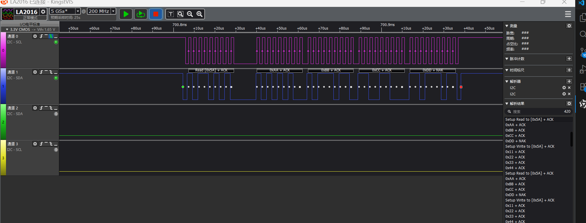
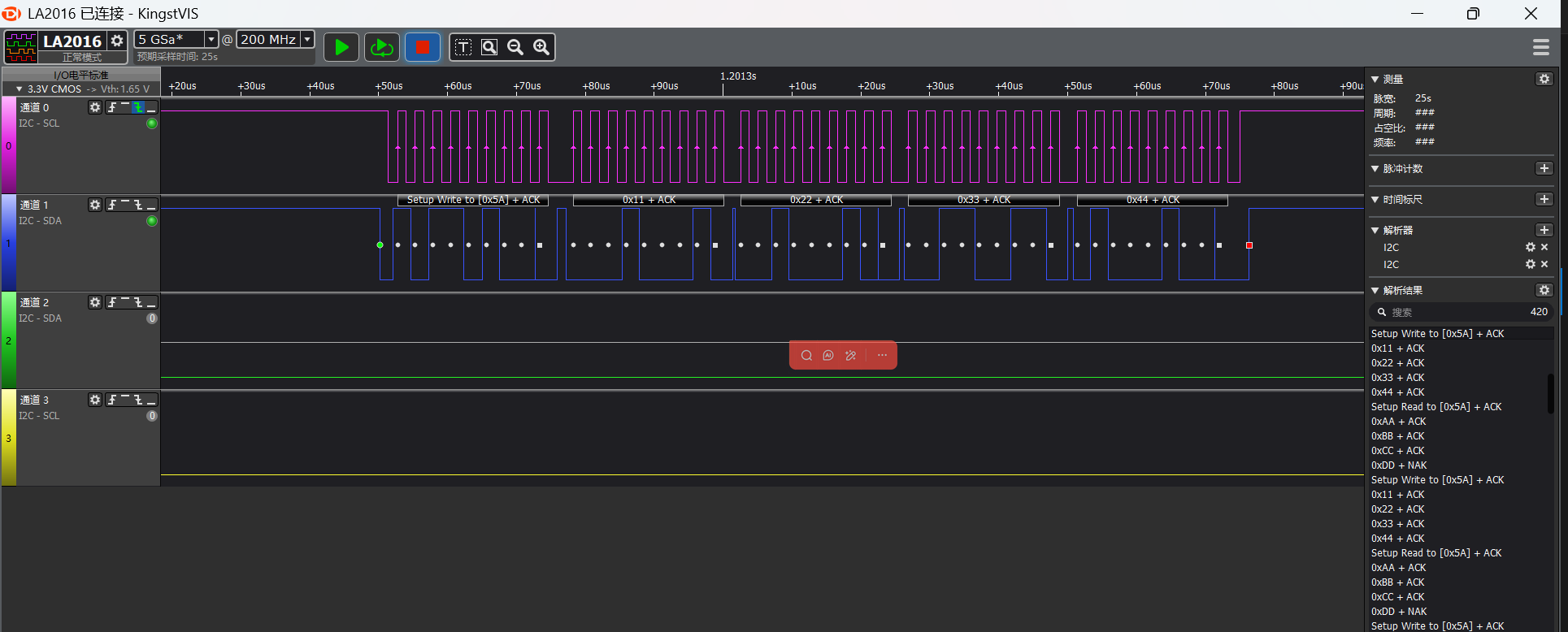
I2C Read/Write Waveforms
Waveforms captured by logic analyzer
I2C master read waveform
I2C master write waveform
I2C Parameter Modification
static I2C_HandleTypeDef hi2c;

#define SLAVE_ADDRESS 0x5A //slave address
uint8_t master_tx_data[] = {0x11, 0x22, 0x33, 0x44};//master send data
uint8_t master_rx_data[4];//master receive data

void I2C_Master_Init(void)
{
    HAL_StatusTypeDef ret;

    //pin nux
#ifdef SF32LB52X
    HAL_RCC_EnableModule(RCC_MOD_I2C2); // enable i2c2
    HAL_PIN_Set(PAD_PA41, I2C2_SCL, PIN_PULLUP, 1); // i2c io select
    HAL_PIN_Set(PAD_PA42, I2C2_SDA, PIN_PULLUP, 1);
#define SLAVE_I2C I2C2// i2c number of cpu
#elif defined(SF32LB58X)
    HAL_RCC_EnableModule(RCC_MOD_I2C6);  // enable i2c6
    HAL_PIN_Set(PAD_PB28, I2C6_SCL, PIN_PULLUP, 0); // i2c io select
    HAL_PIN_Set(PAD_PB29, I2C6_SDA, PIN_PULLUP, 0);
#define SLAVE_I2C I2C6// i2c number of cpu
#elif defined(SF32LB56X)
    HAL_RCC_EnableModule(RCC_MOD_I2C3); // enable i2c3
    HAL_PIN_Set(PAD_PA20, I2C3_SCL, PIN_PULLUP, 1); // i2c io select
    HAL_PIN_Set(PAD_PA12, I2C3_SDA, PIN_PULLUP, 1);
#define SLAVE_I2C I2C3// i2c number of cpu
#endif
    //i2c init
    hi2c.Instance = MASTER_I2C;
    hi2c.Mode = HAL_I2C_MODE_MASTER; // i2c master mode
    hi2c.Init.ClockSpeed = 400000;           // 400kHz
    hi2c.Init.AddressingMode = I2C_ADDRESSINGMODE_7BIT;
    hi2c.Init.GeneralCallMode = I2C_GENERALCALL_DISABLE;

    ret = HAL_I2C_Init(&hi2c);
    if (ret != HAL_OK) {
        rt_kprintf("I2C Master Init failed: %d\n", ret);
        return;
    }
    rt_kprintf("I2C Master Init Success!\n");
}
Based on chip type to distinguish development boards, in the initialization function, for specific chips, configure the corresponding I2C pins
For example, through
#elif defined(SF32LB52X)
chip to determine which development board is being usedThrough
#define EXAMPLE_I2C I2C2
the I2C controller number used by the chip (such as I2C6, I2C3)Through
#define EXAMPLE_I2C_IRQ I2C6_IRQn
the interrupt number corresponding to this I2C controller (for interrupt mode)Finally, use the HAL_PIN_Set() function to configure the I2C SCL and SDA pins, which need to be set to pull-up mode
Note:
Except for 55x chips, PA*_I2C_UART functional IO can be configured to output I2C SDA, SCLK waveforms
The last parameter of HAL_PIN_Set is hcpu/lcpu selection, 1: select hcpu, 0: select lcpu
Troubleshooting
No I2C waveform output
Check against the chip manual whether the CPU’s I2C selection is correct
Check whether the IO configuration and connection are correct