ADC_battery Example
Source path: example/hal/adc/adc_battery
Supported Platforms
This example can run on the following development boards:
sf32lb52-lcd series
sf32lb56-lcd series
sf32lb58-lcd series
Overview
Uses HAL APIs to read battery voltage through a single ADC channel
Usage
Build and Flash
The demo code defaults to single-channel ADC sampling.
Go to the example project directory and run the following SCons command to build:
scons --board=sf32lb52-lcd_n16r8 -j8
Run the flashing command:
build_sf32lb52-lcd_n16r8_hcpu\uart_download.bat
Select the serial port as prompted to download the firmware:
please input the serial port num:5
Output Example
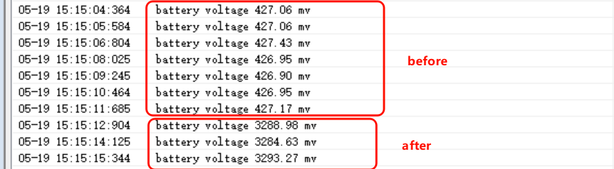
The measured voltage value is printed once per second.
Comparison of logs before and after connecting the battery
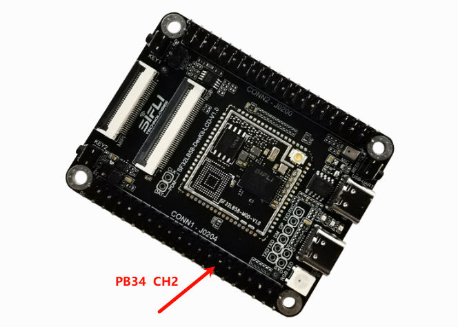
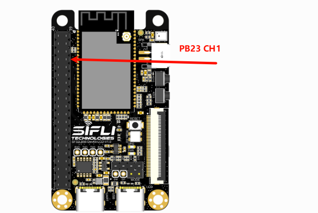
The measurement pin locations for 58_lcd and 56_lcd are:
Measurement point for 58:
Measurement point for 56:
ADC Configuration Flow
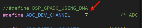
Set the ADC channel that corresponds to the battery Vbat input. Adjust this according to your board platform. The 52-series example uses channel 7.
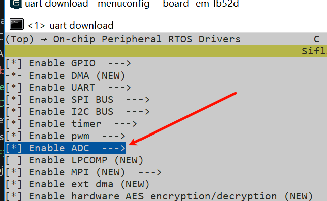
Enable the ADC device in menuconfig
sdk.py menuconfig --board=sf32lb52-lcd_n16r8
Set the ADC channel pin you want to measure to analog input mode (except channel 7 on the 52-series platform)
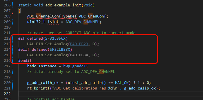
Note:
Enable the corresponding ADC clock source. It is already enabled in the default code, so this step is not mandatory.
/* 2, open adc clock source  */
HAL_RCC_EnableModule(RCC_MOD_GPADC);
ADC calibration
To improve ADC accuracy, SiFli chips are factory-calibrated and the calibration parameters are stored in the OTP area. The calibration method differs across chip families.
To ensure ADC accuracy, this calibration routine should be called once after each power-on. The function below reads the OTP parameters and computes the slopeadc_vol_ratioand offsetadc_vol_offset.
static int utest_adc_calib(void)
After obtaining the raw register value, call
example_adc_get_float_mvto calculate the final voltage using the calibrated slopeadc_vol_ratioand offsetadc_vol_offset.On the 52-series chip, CH8 (Channel 7) is internally connected to Vbat through two equal divider resistors. To obtain the Vbat value, conversion is required. To reduce the error introduced by the divider resistors, the two resistors are factory-calibrated.
static float adc_vbat_factor = 2.01; /* Calibration factor for the two internal divider resistors from CH8 (Channel 7) to Vbat on 52-series chips */
static void example_adc_vbat_fact_calib(uint32_t voltage, uint32_t reg)
{
    float vol_from_reg;

    // Calculate voltage from the register value
    vol_from_reg = (reg - adc_vol_offset) * adc_vol_ratio / ADC_RATIO_ACCURATE;
    adc_vbat_factor = (float)voltage / vol_from_reg;
}
/* Convert the sampled CH8 (Channel 7) value to Vbat voltage, see the code in sifli_get_adc_value */
    float fval = sifli_adc_get_float_mv(fave) * 10; // mv to 0.1mv based
    *value = (rt_uint32_t)fval;
    if (channel == 7)   // for 52x, this channel is fixed for Vbat with a 1/2 divider (calibration required)
        *value = (rt_uint32_t)(fval * adc_vbat_factor); /* Convert the sampled ADC voltage to Vbat voltage */
Troubleshooting
The sampled ADC voltage is incorrect
Check whether the ADC hardware connections are correct. ADC channels map to fixed IO pins and cannot be assigned arbitrarily. Refer to the chip manual for the CH0-CH7 mapping.
The ADC input range is 0V to the reference voltage (3.3V by default on the 52-series). Do not exceed the input range.
Use a debugging tool such as Ozone or LightWork. After starting ADC sampling, connect online and inspect the corresponding register configuration against the chip manual.
ADC accuracy is insufficient
Verify that the ADC calibration parameters are being obtained and applied.
Check whether the divider resistors meet the required accuracy.
Verify that the ADC reference voltage is stable and does not have excessive ripple (see the ADC reference section in the chip manual).
References
EH-SF32LB52X_Pin_config_V1.3.0_20231110.xlsx
DS0052-SF32LB52x Chip Technical Specification V0p3.pdf
Revision History
Version |
Date |
Notes |
|---|---|---|
0.0.1 |
10/2024 |
Initial version |
0.0.2 |
05/2026 |
Added notes for 56 and 58 |