EPIC Example Program
EPIC (ePicasso) is our self-developed graphics engine, a hardware acceleration module specifically designed for 2D/2.5D image processing, mainly used to offload CPU load in image operations and improve image processing efficiency.
Overview
This program is a graphics blending example based on RT-Thread operating system and EPIC. The implemented functions are as follows:
Fill rectangles and crop rectangles for blending display
Gradient color filling
Scale an ezip image
Rotate a normal rgb565 format image + mask function
Single font display
Multi-font blending display
Supported Development Boards
The example can run on the following development boards:
sf32lb52-lchspi-ulp
sf32lb52-nano_52j
sf32lb52-lcd_n16r8
SF32LB56 LCD series
SF32LB58 LCD series
Example Usage
Compilation and Flashing
Switch to the example project directory and run the scons command to compile:
scons --board=sf32lb52-lchspi-ulp -j8
Execute the flashing command:
build_sf32lb52-lchspi-ulp_hcpu\uart_download.bat
Select the port as prompted for download:
please input the serial port num:6
Example Output Result Display:
The LCD screen will cyclically display the following functions:
Fill rectangles and crop rectangles for blending display
Gradient color filling
Scale an ezip image
Rotate a normal rgb565 format image + mask function
Single font display
Multi-font blending display
Example Explanation
Main program flow includes:
Initialize GPU and LCD devices —> Use EPIC corresponding interfaces to process image data –> Output the processed image data to screen display.
Key interfaces used:
1. GPU/EPIC interfaces:
Interface Name |
Function Description |
|---|---|
drv_gpu_open() |
Initialize GPU resources, including interrupts |
drv_epic_fill() |
Fill rectangular area with specified color |
HAL_EPIC_LayerConfigInit() |
Initialize layer configuration structure |
HAL_EPIC_LayerSetDataOffset() |
Set layer data offset (for cropping) |
HAL_EPIC_GetColorDepth() |
Get the pixel depth of the color mode |
drv_epic_blend() |
Execute multi-layer blending operation |
drv_epic_wait_done() |
Wait for blending operation to complete |
drv_epic_fill_grad() |
Execute gradient fill operation |
drv_epic_cont_blend_reset() |
Reset continuous blending state |
drv_epic_cont_blend() |
Execute continuous blending operation |
2. LCD display interfaces:
Interface Name |
Function Description |
|---|---|
rt_device_find(“lcd”) |
Find LCD device |
rt_device_open() |
Open LCD device |
rt_device_control(…, RTGRAPHIC_CTRL_SET_BUF_FORMAT) |
Set display memory format |
rt_device_control(…, RTGRAPHIC_CTRL_GET_INFO) |
Get LCD screen information |
rt_graphix_ops()->draw_rect_async() |
Asynchronously draw rectangle and refresh screen |
Important Notes!!!
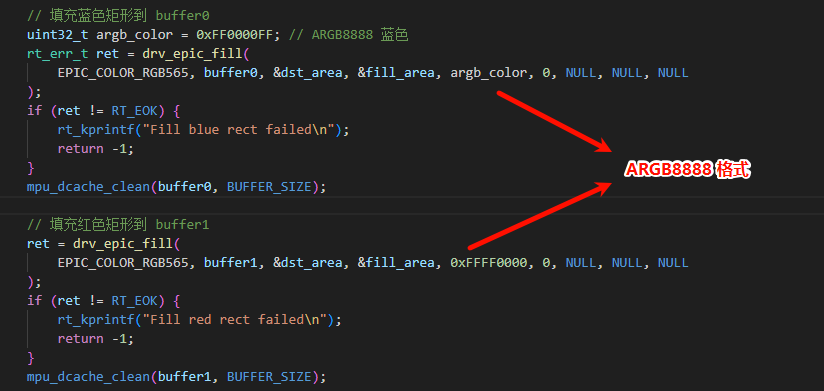
When the screen doesn’t display, check if the fill color is in ARGB8888 format, because the drv_epic_fill interface requires the fill color format to be ARGB8888
 When the image effect doesn’t meet expectations or the screen doesn’t display (as shown in the example): it may be due to improper cropping.

About Cropping
The blending principle of this example is to crop ‘extract’ the fill areas from the fg_layer and bg_layer layers, then place them in an output_layer.
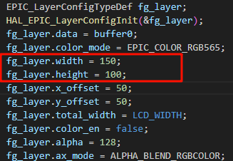
However, it should be noted that when cropping interfaces like HAL_EPIC_LayerSetDataOffset() are not called, the default cropping start position is the first address pointed to by the layer.data pointer, which is the top-left corner (0,0) in this example. Then the cropped area will be (layer.width - 0, layer.height - 0). At this time, if the fill areas we set for the fg_layer and bg_layer layers are not within the cropped area, then our valid data will not be ‘extracted’.
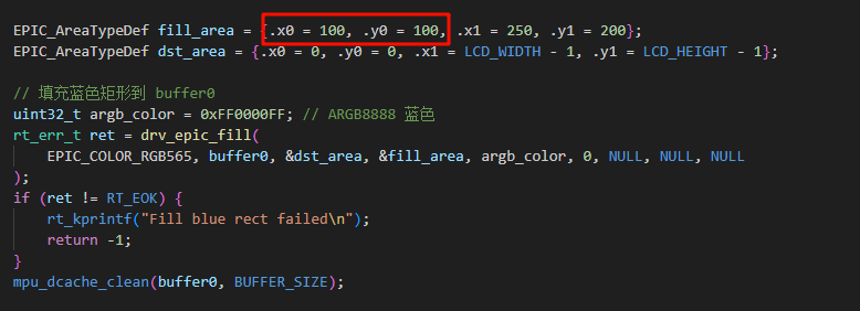
As shown in the code of this example, the fill area is set to (100 ~ 250, 100 ~ 200), and the cropped area is (0 ~ 150, 0 ~ 100). Our fill area perfectly avoids the cropped area, so the data ‘extracted’ by cropping will be empty, only cropping the background.

So how do we both want to set the fill area position and accurately crop ‘extract’ our fill area?
The first and simplest method is to keep the starting position of the fill area consistent with the position of the first address pointed to by the layer.data pointer (that is, put the fill area in the cropped area) without calling any cropping functions.
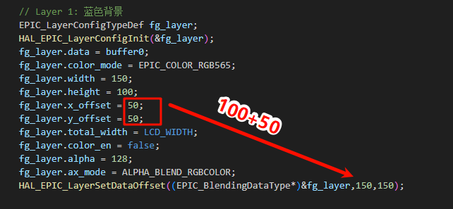
The second method is to call the cropping interface, such as HAL_EPIC_LayerSetDataOffset(EPIC_BlendingDataType *layer, int16_t x, int16_t y), where the parameter layer is the layer to be cropped, x is the x coordinate of the starting position you want to crop, and y is the y coordinate of the starting position you want to crop. This way we can crop wherever we want. It should be noted that the values of x and y need to be added to the values of layer.x_offset and layer.y_offset on the basis of the starting position you want to crop. As shown in this example, the starting position to be cropped is (100,100), and the values of layer.x_offset and layer.y_offset are 50, 50, then our x and y values are 100 + 50 = 150, 100 + 50 = 150.
Important Notes about Mask!!!
When creating a mask layer, the ax_mode format should be selected as ALPHA_BLEND_MASK, and the color_mode value should be consistent with your image data format
On 52x, there are only 2 normal layers + 1 mask layer, and the number of configured normal layers cannot be too many
The pixel alignment standard is: A2 format 4-pixel alignment, A4 format 2-pixel alignment, A8 format no alignment operation required. When the displayed effect does not meet expectations, check whether total_width meets the alignment requirements
If the image display is incorrect and found to be skewed, you can check whether the passed width is consistent with the actual image width. If it’s smaller than the actual width, the vertical lines will skew to the right, and if it’s larger than the actual width, they will skew to the left