I2C EEPROM Example
Source code path: example/rt_device/i2c/eeprom
Supported Platforms
The example can run on the following development boards:
sf32lb52-nano
sf32lb52-lcd series
sf32lb56-lcd series
sf32lb58-lcd series
Overview
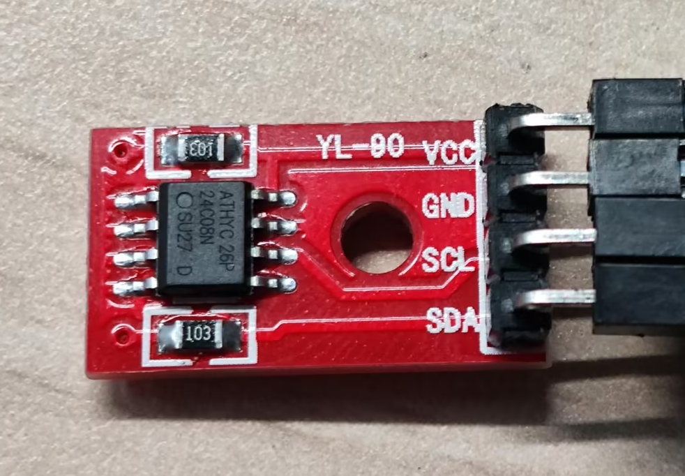
Under RT-Thread operating system, demonstrate the usage of I2C through read and write operations on EEPROM chip AT24CO8SC module
Example Usage
Hardware Connection
Connect VCC and GND of AT24CO8SC to 5v and GND respectively for power supply
Connect SDA and SCK of AT24CO8SC according to the following table based on the development board model
Development Board |
SDA Pin |
SDA Pin Name |
SCL Pin |
SCL Pin Name |
|---|---|---|---|---|
sf32lb52-nano |
3 |
PA42 |
5 |
PA41 |
sf32lb52-lcd |
3 |
PA42 |
5 |
PA41 |
sf32lb56-lcd |
3 |
PA12 |
5 |
PA20 |
sf32lb58-lcd |
3 |
PB29 |
PB28 |
For more detailed pin definitions, please refer to
sf32lb52-nano sf32lb52-lcd sf32lb56-lcd sf32lb58-lcdAT24C08SC
Compilation and Programming
This example uses I2C2. When using RT-Thread operating system, I2C2 peripheral will be virtualized as an rt_device for read and write operations. At this time, you need to confirm whether the
rtconfig.hfile in the project path contains the following 3 macros:
#define RT_USING_I2C 1
#define BSP_USING_I2C 1
#define BSP_USING_I2C2 1
Only when the above three macros are included, the rt_i2c_bus_device_register function will register the "i2c2" rt_device in the rt_hw_i2c_init2 function, and then this device can be successfully found and opened with rt_device_find and rt_device_open.
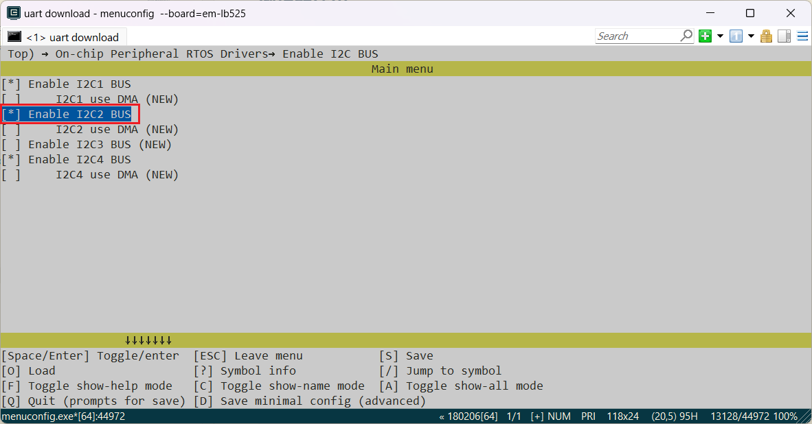
If the above three macros are missing, you need to enable them through the following menuconfig command:
sdk.py menuconfig --board=sf32lb52-lcd_n16r8
As shown in the figure below, select I2C2, save and exit menuconfig, check whether the rtconfig.h macro is generated
SF525 Project Code Compilation
Switch to the example project directory and run the scons command to execute compilation:
scons --board=sf32lb52-lcd_n16r8 -j8
Run build_sf32lb52-lcd_n16r8_hcpu\uart_download.bat, select the port as prompted to download:
build_sf32lb52-lcd_n16r8_hcpu\uart_download.bat

Uart Download

please input the serial port num:5
SF587 Project Code Compilation
Switch to the example project directory and run the scons command to execute compilation:
scons --board=sf32lb58-lcd_n16r64n4 -j8
Switch to the example project/build_xx directory and run download.bat, the program will be automatically downloaded through JLink:
build_sf32lb58-lcd_n16r64n4_hcpu\download.bat
Example Output Results Display:
Log output:
   SFBL
   Serial:c2,Chip:4,Package:3,Rev:3  Reason:00000000
   \ | /
  - SiFli Corporation
   / | \     build on Dec  6 2024, 2.1.7 build 779fe6ee
   2020 - 2022 Copyright by SiFli team
   mount /dev sucess
   [32m][2009] I/drv.rtc: PSCLR=0x80000100 DivAI=128 DivAF=0 B=256
   [0m][32m][2036] I/drv.rtc: RTC use LXT RTC_CR=00000001
   [0m][32m][2058] I/drv.rtc: Init RTC, wake = 0
   [0m][32m][2220] I/drv.audprc: init 00 ADC_PATH_CFG0 0x606
   [0m][32m][2242] I/drv.audprc: HAL_AUDPRC_Init res 0
   [0m][32m][2264] I/drv.audcodec: HAL_AUDCODEC_Init res 0
   [0m][32m][2286] I/TOUCH: Regist touch screen driver, probe=1203b8b1
   [0m]call par CFG1(3313)
   fc 9, xtal 2000, pll 2123
   call par CFG1(3313)
   fc 7, xtal 2000, pll 1698
   main!!
   [2448] D/eeprom_i2c: Start i2c eeprom rtt demo!
   i2c_bus:0x20007f50
   Find i2c bus device I2C2
   [2492] D/eeprom_i2c: i2c write reg:0x1,data:0x11,ret:1
   [2681] D/eeprom_i2c: i2c write reg:0x2,data:0x22,ret:1
   [2869] D/eeprom_i2c: i2c write reg:0x3,data:0x33,ret:1
   [3058] D/eeprom_i2c: i2c write reg:0x4,data:0x44,ret:1
   [3248] D/eeprom_i2c: i2c read reg:0x1,pdata:0x11,ret:1
   [3273] D/eeprom_i2c: i2c read reg:0x2,pdata:0x22,ret:1
   [3298] D/eeprom_i2c: i2c read reg:0x3,pdata:0x33,ret:1
   [3323] D/eeprom_i2c: i2c read reg:0x4,pdata:0x44,ret:1
   [3345] D/eeprom_i2c: i2c end!
   msh />
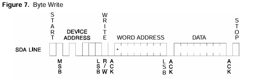
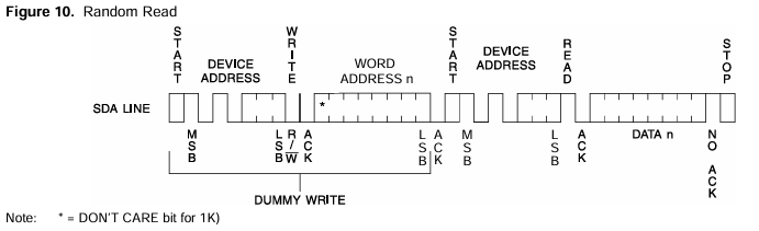
I2C read/write waveforms required by AT24C08SC chip manual
I2C write waveform
I2C read waveform
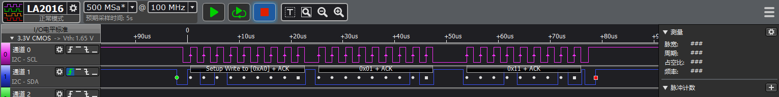
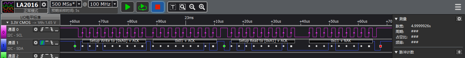
Partial waveforms captured by logic analyzer
I2C write waveform
I2C read waveform
I2C Parameter Modification
See comments in EEPROM_init function
unsigned char EEPROM_init(void)
{

    uint8_t slaveAddr = EEPROM_I2C_ADDRESS; // 7bit address of device
    HAL_StatusTypeDef ret;

    //1. pin mux
#ifdef SF32LB52X
    HAL_PIN_Set(PAD_PA41, I2C2_SCL, PIN_PULLUP, 1); // i2c io select
    HAL_PIN_Set(PAD_PA42, I2C2_SDA, PIN_PULLUP, 1);
#elif defined(SF32LB58X)
    HAL_PIN_Set(PAD_PB28, I2C6_SCL, PIN_PULLUP, 1); // i2c io select
    HAL_PIN_Set(PAD_PB29, I2C6_SDA, PIN_PULLUP, 1);
#endif

    // 2. i2c init
    // find i2c2
#ifdef SF32LB52X
    i2c_bus = rt_i2c_bus_device_find("i2c2");
#elif defined(SF32LB58X)
    i2c_bus = rt_i2c_bus_device_find("i2c6");
#endif

    rt_kprintf("i2c_bus:0x%x\n", i2c_bus);
    if (i2c_bus)
    {
        #ifdef SF32LB52X
        rt_kprintf("Find i2c bus device I2C2\n");
        #elif defined(SF32LB58X)
        rt_kprintf("Find i2c bus device I2C6\n");
        #endif
        // open rt_device i2c2
        rt_device_open((rt_device_t)i2c_bus, RT_DEVICE_FLAG_RDWR);
        //rt_i2c_open(i2c_bus, RT_DEVICE_FLAG_RDWR);
        struct rt_i2c_configuration configuration =
        {
            .mode = 0,
            .addr = 0,
            .timeout = 500, //Waiting for timeout period (ms)
            .max_hz = 400000, //I2C rate (hz)
        };
        // config I2C parameter
        rt_i2c_configure(i2c_bus, &configuration);
    }
    else
    {
        #ifdef SF32LB52X
        LOG_E("Can not found i2c bus I2C2, init fail\n");
        #elif defined(SF32LB58X)
        LOG_E("Can not found i2c bus I2C6, init fail\n");
        #endif
        return -1;
    }
    return 0;
}
When opening rt_device device, if using rt_i2c_open function, no functional issues are found, but when using
list_device,i2c2will not show open status:
rt_i2c_open(i2c_bus, RT_DEVICE_FLAG_RDWR);
    msh />
 TX:list_device
    list_device
    device           type         ref count
    -------- -------------------- ----------
    audcodec Sound Device         0
    audprc   Sound Device         0
    rtc      RTC                  0
    pwm3     Miscellaneous Device 0
    touch    Graphic Device       0
    lcdlight Character Device     0
    lcd      Graphic Device       0
    i2c4     I2C Bus              0
    i2c2     I2C Bus              0
    i2c1     I2C Bus              0
    lptim1   Timer Device         0
    btim1    Timer Device         0
    uart1    Character Device     2
    pin      Miscellaneous Device 0
    msh />
When using rt_device_open:
rt_device_open((rt_device_t)i2c_bus, RT_DEVICE_FLAG_RDWR);
    msh />
 TX:list_device
    list_device
    device           type         ref count
    -------- -------------------- ----------
    audcodec Sound Device         0
    audprc   Sound Device         0
    rtc      RTC                  0
    pwm3     Miscellaneous Device 0
    touch    Graphic Device       0
    lcdlight Character Device     0
    lcd      Graphic Device       0
    i2c4     I2C Bus              0
    i2c2     I2C Bus              1
    i2c1     I2C Bus              0
    lptim1   Timer Device         0
    btim1    Timer Device         0
    uart1    Character Device     2
    pin      Miscellaneous Device 0
This only demonstrates one usage of I2C. When the waveform required by I2C peripheral is inconsistent with the example, you can refer to the usage of rt_i2c_transfer function.
Note:
Except for SF32LB55x chips, all PA ports support HCPU I2C SDA and SCL functions, all PB ports support LCPU I2C SDA and SCL functions
HCPU PA ports cannot be configured for LCPU I2C instances, and LCPU PB ports cannot be configured for HCPU I2C usage. For example, I2C5 is an LCPU I2C instance, its SCL and SDA pins cannot be mapped to PA ports
The last parameter of HAL_PIN_Set is for hcpu/lcpu selection, 1: select hcpu, 0: select lcpu
Exception Diagnosis
No I2C waveform output
Use
pin status 39command to check the corresponding PA39, PA40 IO status FUNC is correct, VAL level should be 1
    msh />
 TX:pin status 39
    pin status 39
    [32m][215653658] I/TEST.GPIO: PIN 39, FUNC=4, VAL=1, DIG_IO_PU, GPIO_MODE_INPUT, irqhdr=/, arg=/
    [0m]
    msh />
    msh />
 TX:pin status 40
    pin status 40
    [32m][215753678] I/TEST.GPIO: PIN 40, FUNC=4, VAL=1, DIG_IO_PU, GPIO_MODE_INPUT, irqhdr=/, arg=/
    [0m]
    msh />
    msh />
Use ‘list_device’ command to check if ‘i2c2’ device exists and is opened
Check if IO configuration and connection are correct
Continuous write failure, I2C waveform normal, no acknowledgment signal
AT24C08SC write input requires up to 5ms Write Cycle Time waiting for data programming
void EEPROM_test(void)
{
    unsigned char i = 0;

    for ( i = 0; i < 4; i++)
    {
        EEPROM_write_data(TEST_ADDR[i], TEST_DATA[i]);
        delayms(5); //5ms delay for AT240C8SC write time cycle
    }

    for ( i = 0; i < 4; i++)
    {
        EEPROM_read_data(TEST_ADDR[i], &RECEIVED);
    }
}
Reference Documents
Update Log
Version |
Date |
Release Notes |
|---|---|---|
0.0.1 |
10/2024 |
Initial version |