Power Management
The Power Management module is developed based on the RT-Thread power management framework. It helps minimize the effort required for users to implement low-power functionality. In addition to the RT-Thread power management API, users can also use this module to implement their own low-power designs. Butterfli includes three subsystems (power domains): HPSYS (HCPU internal), LPSYS (LCPU internal), and BLESYS (BCPU internal). Each subsystem can independently enter its own low-power mode.
Currently, four low-power modes are supported. IDLE is the lowest power mode, while STANDBY is the highest low-power mode. Starting from the LIGHT mode, subsystems are inaccessible in low-power mode.
PM_SLEEP_MODE_IDLE: CPU executes the WFE instruction, waiting for events or IRQ.PM_SLEEP_MODE_LIGHT: Subsystem enters light sleep mode.PM_SLEEP_MODE_DEEP: Subsystem enters deep sleep mode.PM_SLEEP_MODE_STANDBY: Subsystem enters standby mode.
When entering the idle loop, the RT-Thread power management framework selects the appropriate low-power mode based on how long the CPU has been idle.
The default power mode selection method uses the pm policy table to decide the low-power mode. The default pm policy table can be overridden. Additionally, the default power mode selection method can be replaced by a user-defined algorithm.
Users can block the system from entering low-power modes higher than PM_SLEEP_MODE_IDLE by calling rt_pm_request, even if the CPU has been idle for a long time, such as when DMA transfer is ongoing or a thread is suspended waiting for a completion signal.
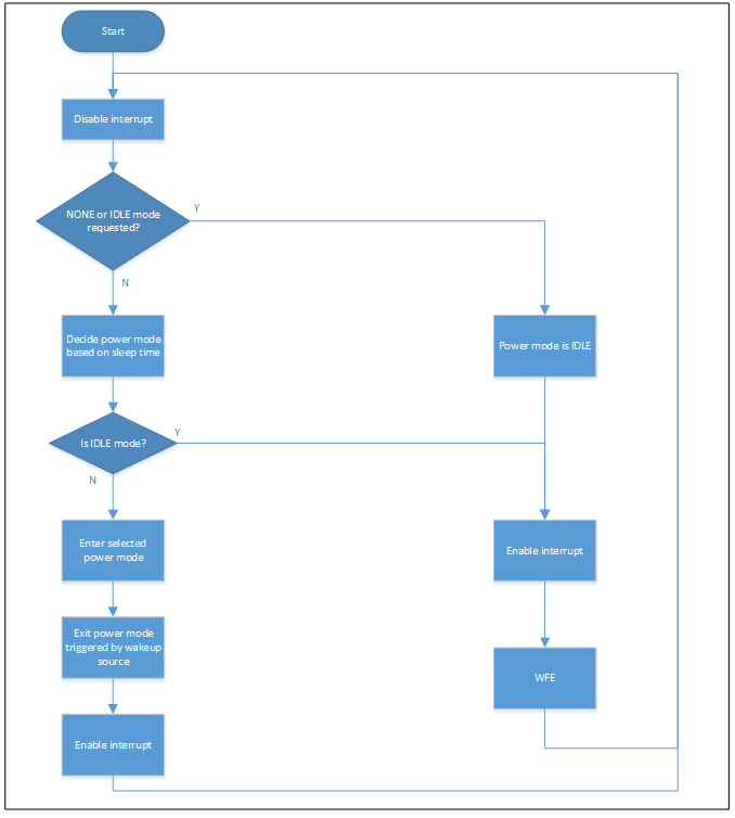
If PM_SLEEP_MODE_IDLE or PM_SLEEP_MODE_NONE is requested, the system will stay in PM_SLEEP_MODE_IDLE after entering the idle loop. If PM_SLEEP_MODE_LIGHT, PM_SLEEP_MODE_DEEP, or PM_SLEEP_MODE_STANDBY is requested, it will not affect the low-power mode selection result.
Below is the timing diagram of the idle loop.
pm_request Example
The following example demonstrates how to prevent the system from entering higher low-power modes, even when sleep time conditions are met.
rt_device_t uart_device;
rt_err_t tx_done(rt_device_t dev, void *buffer)
{
    rt_sem_release(sema);
}

void init(void)
{
    uart_device = rt_device_find("uart1");
    rt_device_set_tx_complete(uart_device, tx_done);
    rt_device_open(uart_device, RT_DEVICE_OFLAG_RDWR | RT_DEVICE_FLAG_DMA_TX | RT_DEVICE_FLAG_DMA_RX);
}

void start_tx(void)
{
    rt_pm_request(PM_SLEEP_MODE_IDLE);
    /* start UART transmission in DMA mode */
    rt_device_write(uart_device, 0, buf, len);
    /* wait for transmission complete
     * though sleep time is very long (larger than the threshold of STANDBY mode), system will stay in IDLE mode
     */
    rt_sem_take(sema, RT_WAITING_FOREVER);
    /* IDLE mode is released, then system has a chance to enter a higher low-power mode */
    rt_pm_release(PM_SLEEP_MODE_IDLE);
};
Default PM Policy Table
Following is default PM Policy Table. The threshold for sleep time is used to determine the highest power mode for low-power selection. The sleep time is calculated based on the operating system timer, i.e., the most recent timer timeout tick is compared with the current tick (using rt_timer_next_timeout_tick() and rt_tick_get()).
For example, if the sleep time is 20ms, which is greater than 15ms (threshold for PM_SLEEP_MODE_LIGHT) but less than 25ms (threshold for PM_SLEEP_MODE_DEEP), PM_SLEEP_MODE_LIGHT is selected as the low-power mode.
If the sleep time is 50ms, exceeding both 15ms and 25ms, the system enters PM_SLEEP_MODE_DEEP.
const static pm_policy_t default_pm_policy[] =
{
    {15, PM_SLEEP_MODE_LIGHT},
    {25, PM_SLEEP_MODE_DEEP},
    {10000, PM_SLEEP_MODE_STANDBY},
};

/** pm policy item structure */
typedef struct
{
    uint32_t    thresh;      /**< sleep time threshold in millisecond */
    uint8_t     mode;        /**< power mode chosen if sleep time threshold is satisfied */
} pm_policy_t;
Custom RT-Thread Power Management API
rt_pm_policy_register: Register user-defined policies to override default values.rt_pm_override_mode_select: Register a user-defined power mode selection method to override the default.rt_pm_request/rt_pm_release: Prevent entry into LIGHT/DEEP/STANDBY modes.rt_application_get_power_on_mode: Get the system’s power-on mode, e.g., if the code was started from standby mode or woken up.
PM Module API
pm_enable_pin_wakeup/pm_disable_pin_wakeup: Specify a pin to wake up the subsystem.pm_get_power_mode: Get the last low-power mode.pm_get_wakeup_src: Get the last wake-up source.aon_irq_handler_hook: AON IRQ handler hook function. Users can re-implement this hook to execute custom operations.pm_shutdown: Shut down the system.
Inter-Subsystem Access
If a subsystem is in LIGHT, DEEP, or STANDBY low-power mode, other subsystems cannot access it. If an illegal access occurs, a hard fault exception is triggered. To access resources from another subsystem in a low-power mode, the target subsystem must be awakened first. The hardware mailbox can automatically wake up the target subsystem. Its driver implementation takes low-power features into account. When using the hardware mailbox driver for inter-processor communication, the driver ensures memory access when the accessed subsystem is in ACTIVE or IDLE mode. The sending driver writes data to its buffer and notifies the receiver. The sending subsystem will not enter any low-power mode other than idle until the receiving subsystem consumes the data, i.e., the sender’s ring buffer is empty.
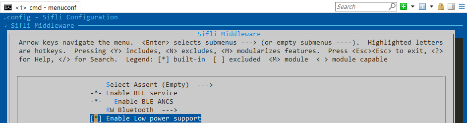
Configuration
This module can be enabled in the SiFli Middleware menu, which automatically enables RT_USING_PM.
#define BSP_USING_PM
#define RT_USING_PM