Inter-Core Communication Queue
The Inter-Core Communication Queue (IPC Queue library) implements bidirectional inter-core communication functionality. It combines the notification mechanism of mailbox with a software circular buffer, making inter-core communication similar to serial communication between two chips. The library supports up to 4 queues operating simultaneously. Each queue is bound to a pair of transmit and receive buffers (buffers are optional; if set to NULL, only interrupt notification functionality is provided). The queues are mapped to corresponding hardware channels according to user configuration. The platform-supported hardware channel numbers can be found in the corresponding ipc_hw_port.h.
Taking the communication between HCPU and LCPU as an example, from ipc_hw_port.h we know that channels 0~7 are hardware channels between HCPU and LCPU. By selecting channel 0, calling ipc_queue_init() configures the addresses of the transmit and receive buffers and the callback function for receiving. If successful, it returns a valid queue handle. Then, calling ipc_queue_open() opens the channel, and data can be transmitted and received normally.
By calling ipc_queue_write(), data can be sent to the opposite end. The data will be written to the configured tx_buffer, and the receiver will receive an interrupt notification (the receiver has already opened the corresponding IPC queue). If the opposite end sends data, the receive callback registered in ipc_queue_init() will be triggered, and you can call ipc_queue_read() to read data from the rx_buffer.
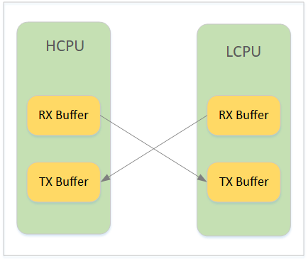
It is important to note that the rx_buffer address configured for HCPU should be the same as the tx_buffer_alias address configured for LCPU, i.e., pointing to tx_buffer. Similarly, the tx_buffer_alias configured for HCPU should be the same as the rx_buffer address for LCPU. tx_buffer must be the RAM address of the subsystem where the sender is located. In other words, HCPU needs to allocate a buffer in its own RAM space as the sending buffer, so data can still be written even if the opposite subsystem has not been woken up. tx_buffer is managed by the sender. Since the receiver may not be able to directly access the sender’s address space, the tx_buffer_alias is used to specify the address space of the tx_buffer that is accessible to the receiver. The two addresses point to the same physical buffer.
The relationship between tx_buffer and rx_buffer is shown in Figure 1.
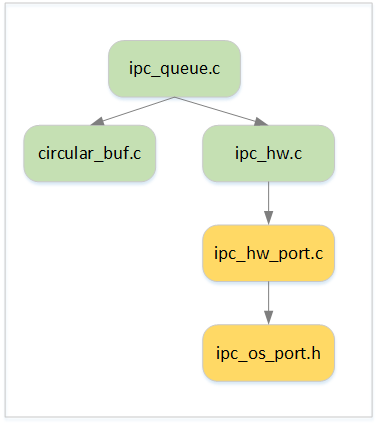
The architecture of the library is shown in Figure 2. The API interfaces are defined in ipc_queue.h, with platform-independent implementation in ipc_queue.c. ipc_hw.c encapsulates the ButterFli’s mailbox interface and provides interrupt services for ipc_queue.c. However, since different ButterFli chip series have different hardware channel configurations, each chip has its own ipc_hw_port.c, which defines the variable ipc_hw_obj to describe the hardware channel and implements the interrupt handling function.
The ipc_queue.c provides the interface ipc_queue_data_ind for the interrupt handler to notify the upper layer of new data arrival.
For the RT-Thread platform, you can use the API provided by ipc_queue_device to encapsulate IPC Queue into an RT Device.
Note
#ipc_queue_read and #ipc_queue_write are not thread-safe. If ipc_queue_read or ipc_queue_write is called in a multi-threaded environment on the same queue, the caller must ensure mutual exclusion to avoid re-entry.
However, if accessing different queues, no mutual exclusion is needed. For example, thread_1 writes data to queue_0 using ipc_queue_write, while thread_2 writes data to queue_1 using ipc_queue_write. Since different queues are being operated, no mutual exclusion is required. However, if both threads are writing data to queue_0, mutual exclusion must be ensured before calling ipc_queue_write.
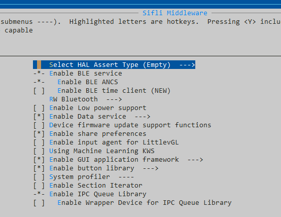
Configuration
Enable the IPC Queue library by selecting SiFli Middleware -> Enable IPC Queue Library in the configuration menu.
Usage Example
The following test code demonstrates using hardware channel 0 as the bidirectional communication channel between HCPU and LCPU. The HCPU’s address 0x20000000 is used as the send buffer, and the LCPU’s address 0x20100000 is used as the LCPU’s send buffer. HCPU_ADDR_2_LCPU_ADDR is used to convert the HCPU address to the LCPU address space, and LCPU_ADDR_2_HCPU_ADDR does the reverse.
HCPU Code Snippet:
static int32_t hcpu_rx_ind(ipc_queue_handle_t ipc_queue, size_t size)
{
}

void hcpu_queue_test(void)
{
    ipc_queue_cfg_t q_cfg;
    ipc_queue_handle_t q_handle;
    uint32_t buf[32];

    q_cfg.qid = 0;  /* Use hardware channel 0 */
    q_cfg.tx_buf_size = 0x100;
    q_cfg.tx_buf_addr = 0x20000000;
    q_cfg.tx_buf_addr_alias = HCPU_ADDR_2_LCPU_ADDR(0x20000000);
    q_cfg.rx_buf_addr = LCPU_ADDR_2_HCPU_ADDR(0x20100000);
    q_cfg.rx_ind = hcpu_rx_ind;
    q_cfg.user_data = 0;

    q_handle = ipc_queue_init(&q_cfg);

    ipc_queue_open(q_handle);
    /* Send data to LCPU */
    ipc_queue_write(q_handle, buf, sizeof(buf), 10);
}
LCPU Code Snippet:
uint8_t lcpu_rx_data_size;
static int32_t lcpu_rx_ind(ipc_queue_handle_t ipc_queue, size_t size)
{
    lcpu_rx_data_size = size;
}

void lcpu_queue_test(void)
{
    ipc_queue_cfg_t q_cfg;
    ipc_queue_handle_t q_handle;
    uint8_t *buffer;

    q_cfg.qid = 0;   /* Use hardware channel 0 */
    q_cfg.tx_buf_size = 0x100;
    q_cfg.tx_buf_addr = 0x20100000;
    q_cfg.tx_buf_addr_alias = LCPU_ADDR_2_HCPU_ADDR(0x20100000);
    q_cfg.rx_buf_addr = HCPU_ADDR_2_LCPU_ADDR(0x20000000);
    q_cfg.rx_ind = lcpu_rx_ind;
    q_cfg.user_data = 0;

    q_handle = ipc_queue_init(&q_cfg);
    ipc_queue_open(q_handle);

    while (0 == lcopu_rx_data_size)
    {
        /* Wait for data */
    }

    buffer = malloc(lcpu_rx_data_size);
    /* Read data */
    ipc_queue_read(q_handle, buffer, lcpu_rx_data_size);

    /* Handle data */
    ...

    free(buffer)
}