ADC Example
Source code path: example\rt_device\adc\channel
Warning
Not verified
Supported Platforms
The example can run on the following development boards.
sf32lb52-lcd_n16r8
sf32lb52-lcd_52d
sf32lb58-lcd_n16r64n4
Overview
Under RT-Thread operating system, ADC single-channel sampling demonstration
Example Usage
Compilation and Flashing
This example uses ADC. Under RT-Thread operating system, ADC peripheral is virtualized as an rt_device for read/write operations. At this time, you need to confirm whether the
rtconfig.hfile in the current path contains the following 2 macros:
#define BSP_USING_ADC 1 #define BSP_USING_ADC1 1 #define RT_USING_ADC 1
Only when the above three macros are included, the sifli_adc_init function will register the "bat1" rt_device through the rt_hw_adc_register function, and then the device can be successfully found with rt_device_find and controlled with rt_device_control.
Note
SiFli series MCUs support timer interrupt to trigger multi-channel simultaneous sampling. You can refer to the definition within macro BSP_GPADC_SUPPORT_MULTI_CH_SAMPLING and the chip user manual
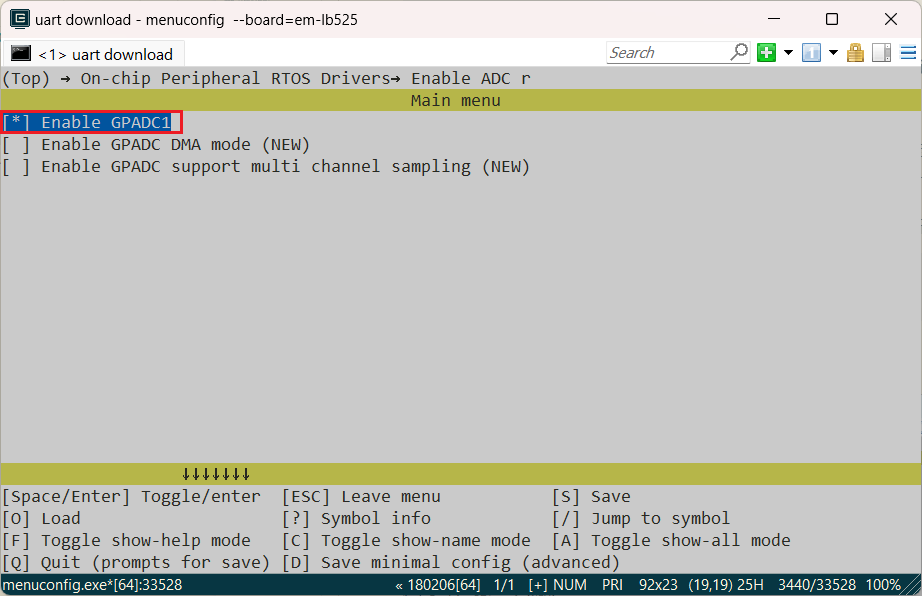
If the above three macros are missing, you need to enable them through
menuconfigwith the following command
sdk.py menuconfig –board=sf32lb52-lcd_n16r8 525 development board sdk.py menuconfig –board=sf32lb52-lcd_52d 52d development board sdk.py menuconfig –board=sf32lb58-lcd_n16r64n4 587 development board
As shown in the figure below, select GPADC1, save and exit menuconfig, check if the rtconfig.h macro is generated
Switch to the example project directory and run the scons command to compile:
scons –board=em-‘bread nmae’ -j8
Switch to the example
project/build_xxdirectory and runuart_download.bat, select the port as prompted to download:
build_sf32lb52-lcd_n16r8_hcpu\uart_download.bat
Uart Download
please input the serial port num:5
sf32lb58-lcd_n16r64n4 Flashing
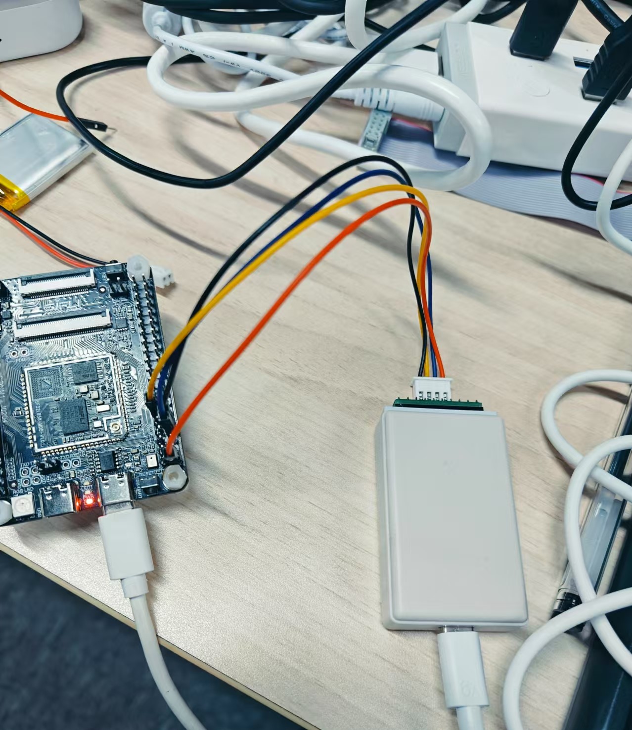
sf32lb58-lcd_n16r64n4 flashing is different from 52 series flashing and requires J-link for flashing. Connect J-link with development board and PC
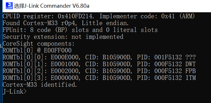
 In J-Link Commander, input ‘connect’ and ‘?’ commands to select the corresponding model to complete connection. Successful connection is shown below:
 After successful connection, return to ConEmu and input ‘build_sf32lb58-lcd_n16r64n4_hcpu\download.bat’ for flashing
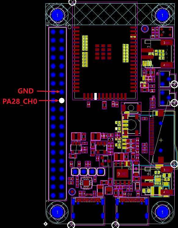
Hardware Connection (52 Series)
PA28 is the fixed output IO for ADC1 Channel 0
Hardware Connection (587)
PB34 is the fixed output IO for ADC1 Channel 2

Example Output Results Display:
Log output:
   SFBL
   Serial:c2,Chip:4,Package:3,Rev:3  Reason:00000080
    \ | /
   - SiFli Corporation
    / | \     build on Nov  5 2024, 2.2.0 build 00000000
    2020 - 2022 Copyright by SiFli team
   mount /dev sucess
   [32m][490] I/drv.rtc: PSCLR=0x80000100 DivAI=128 DivAF=0 B=256
   [0m][32m][516] I/drv.rtc: RTC use LXT RTC_CR=00000001
   [0m][32m][538] I/drv.rtc: Init RTC, wake = 1
   [0m][32m][565] I/drv.audprc: init 00 ADC_PATH_CFG0 0x606
   [0m][32m][587] I/drv.audprc: HAL_AUDPRC_Init res 0
   [0m][32m][608] I/drv.audcodec: HAL_AUDCODEC_Init res 0
   [0m][32m][630] I/TOUCH: Regist touch screen driver, probe=1203bf69
   [0mcall par CFG1](35bb)
   fc 9, xtal 2000, pll 2051
   call par CFG1(35bb)
   fc 9, xtal 2000, pll 2051
   Start adc demo!
   adc control origin data 2783, Voltage 20846
   [32m][828] I/adc: adc channel:0,value:20846
   [0m]msh />[32m][1567] I/adc: rt_adc_read:0,value:20700
   [0m]spi adc end!
The log printed value is in 0.1mV units, 20846 equals 2084.6mV or 2.0846V
ADC Configuration Process
Ensure the
rtconfig.hfile contains the following 4 macros:
#define BSP_USING_ADC 1 #define BSP_USING_ADC1 1 #define RT_USING_ADC 1
Configure PA28 port corresponding to ADC1 Channel 0
    \* set pinmux of channel 0 to analog input *\
    HAL_PIN_Set_Analog(PAD_PA28, 1);
Note
ADC input ports are fixed IO ports, as shown in the figure below:
52 chip ADC CH1-7 distribution, corresponding to software configured Channel0-6, the last channel CH8(Channel 7) is internally connected to battery Vbat detection and is not mapped to external IO

HAL_PIN_SetHAL_PIN_Set_Analogthe last parameter is for hcpu/lcpu selection, 1: select hcpu, 0: select lcpu
Use
rt_device_findandrt_device_controlsequentially to find and configure thebat1device interface function.rt_adc_opsdoes not definert_device_open, so not executingrt_device_openwill not affect ADC functionality, it will only affect whetherbat1shows open status inlist_device
#define ADC_DEV_NAME        "bat1"      /* ADC1 device, already registered in rt_hw_adc_register function, cannot be modified arbitrarily */
#define ADC_DEV_CHANNEL     0           /* ADC channel selection PA28 fixed to CH1(Channel 0) */
//#define REFER_VOLTAGE       330         /* ADC reference voltage, 52 chip can choose 1v8 or 3v3, interface is not currently open, fixed to 3V3 */
static rt_device_t s_adc_dev; /* Define an rt_device device */
static rt_adc_cmd_read_arg_t read_arg;

void adc_example(void)
{
    rt_err_t r;

    /* Configure PA28 as analog input IO and cannot enable internal pull-up/pull-down */
    HAL_PIN_Set_Analog(PAD_PA28, 1);

    /* Find bat1 device, if BSP_USING_ADC1 is not enabled, device will not be found and system will hang */
    s_adc_dev = rt_device_find(ADC_DEV_NAME);

    /* Configure sampling channel to channel 0*/
    read_arg.channel = ADC_DEV_CHANNEL;

    r = rt_adc_enable((rt_adc_device_t)s_adc_dev, read_arg.channel);

    /* This interface will call sifli_adc_control function, read only once, users can process data themselves */
    r = rt_device_control(s_adc_dev, RT_ADC_CMD_READ, &read_arg.channel);
    /* Log printed value is in 0.1mV units, 20846 equals 2084.6mV or 2.0846V  */
    LOG_I("adc channel:%d,value:%d",read_arg.channel,read_arg.value); /* (0.1mV), 20846 is 2084.6mV or 2.0846V */

    /* This demonstrates another way to perform ADC sampling, this interface will call sifli_get_adc_value function, will perform default 22 times averaging  */
    rt_uint32_t value = rt_adc_read((rt_adc_device_t)s_adc_dev, ADC_DEV_CHANNEL);
    /* Log printed value is in 0.1mV units, 20700 equals 2070.0mV or 2.0700V  */
    LOG_I("rt_adc_read:%d,value:%d",read_arg.channel,value); /* (0.1mV), 20700 is 2070mV or 2.070V */

    /* After sampling is complete, close adc */
    rt_adc_disable((rt_adc_device_t)s_adc_dev, read_arg.channel);

}
Exception Diagnosis
Program crashes with the following log
   Start adc demo!
   Assertion failed at function:rt_adc_enable, line number:144 ,(dev)
   Previous ISR enable 0
Reason:
BSP_USING_ADC1 is not defined, causing rt_hw_adc_register function to not register "bat1", and Assert crashes when rt_device_find searches for this device
Ensure the rtconfig.h file contains the following 3 macros:
#define BSP_USING_ADC 1
#define BSP_USING_ADC1 1
#define RT_USING_ADC 1
ADC sampled voltage value is incorrect
Use
pin status 28command to check the corresponding PA28 IO status, whether it matches the following
     msh />
 TX:pin status 28
    pin status 28
    [32m][372862432] I/TEST.GPIO: PIN 28, FUNC=15, VAL=0, ANA_IN, GPIO_MODE_INPUT, irqhdr=/, arg=/
    [0m]msh />
Use
list_devicecommand to check ifbat1device exists. ADC driver does not affect ADC functionality whenbat1device is not opened withrt_device_open
    msh />
 TX:list_device
    list_device
    device           type         ref count
    -------- -------------------- ----------
    audcodec Sound Device         0
    audprc   Sound Device         0
    rtc      RTC                  0
    pwm3     Miscellaneous Device 0
    pwm2     Miscellaneous Device 0
    touch    Graphic Device       0
    lcdlight Character Device     0
    lcd      Graphic Device       0
    bat1     Miscellaneous Device 0
    i2c4     I2C Bus              0
    i2c1     I2C Bus              0
    spi1     SPI Bus              0
    lptim1   Timer Device         0
    btim1    Timer Device         0
    gptim1   Timer Device         0
    uart2    Character Device     0
    uart1    Character Device     2
    pin      Miscellaneous Device 0
    msh />
Check if ADC hardware is connected correctly. ADC sampling channels are fixed IO ports and cannot be specified arbitrarily. For specific CH0-7 IO assignments, refer to the chip manual
ADC input voltage range is 0V - reference voltage (52 defaults to 3v3), cannot exceed input range
ADC accuracy is insufficient
Whether ADC calibration parameters are obtained and used
Whether the accuracy of voltage divider resistors meets requirements
Whether ADC reference voltage is stable and has excessive ripple (refer to ADC voltage reference chip manual for details)
Reference Documents
EH-SF32LB52X_Pin_config_V1.3.0_20231110.xlsx
DS0052-SF32LB52x-芯片技术规格书 V0p3.pdf
RT-Thread Official Website
https://www.rt-thread.org/document/site/#/rt-thread-version/rt-thread-standard/programming-manual/device/adc/adc
Update History
Version |
Date |
Release Notes |
|---|---|---|
0.0.1 |
11/2024 |
Initial version |