LCDC
LCDC (LCD Controller) provides a unified interface for displays without needing to concern about specific physical connections like SPI, parallel interface, or other physical connections. Only the physical interface and parameters need to be configured during initialization, and afterwards a unified interface is used.
Additionally, it supports layer alpha blending. Layers are as follows (in stacking order):
Solid color background
Layer 0
Layer 1 (52x not supported)
Supported Physical Interfaces:
Name |
55X |
58X |
56X |
52X |
|---|---|---|---|---|
3SPI (1/2 data line) |
Y |
Y |
Y |
Y |
4SPI (1/2 data line) |
Y |
Y |
Y |
Y |
QAD-SPI |
Y |
Y |
Y |
Y |
DSI Command Mode |
Y |
Y |
N |
N |
DSI Video Mode |
N |
Y |
N |
N |
AHB output to SRAM/PSRAM |
Y |
Y |
Y |
Y |
DBI 8080-8bit |
Y |
Y |
Y |
Y |
JDI |
Y |
Y |
Y |
Y |
DPI |
Y |
Y |
Y |
Y |
Supported Speeds:
SPI (including 3SPI, 4SPI, QAD-SPI) speed = HCLK/divider, where divider is 2~255
DSI only supports several speeds configured by DSI_Clock_Freq
DBI same as SPI
Supported Color Output Formats
RGB332
RGB565
RGB888
RGB565_SWAP (55x not supported)
Layer Supported Color Formats
RGB332
RGB565
RGB888
ARGB8888
ARGB8565
A8 (55x not supported)
L8 (55x not supported)
RGB565_SWAP (55x not supported)
bit31~bit25 |
bit24~bit17 |
bit16~bit8 |
bit7~bit0 |
|
|---|---|---|---|---|
RGB332 |
/ |
/ |
/ |
R2~R0G2~G0B1~B0 |
RGB565 |
/ |
/ |
R4~R0G5~G3 |
G2~G0B4~B0 |
RGB565_SWAP |
/ |
/ |
G2~G0B4~B0 |
R4~R0G5~G3 |
ARGB8565 |
/ |
A7 ~ A0 |
R4~R0G5~G3 |
G2~G0B4~B0 |
RGB888 |
/ |
R7 ~ R0 |
G7 ~ G0 |
B7 ~ B0 |
ARGB8888 |
A7 ~ A0 |
R7 ~ R0 |
G7 ~ G0 |
B7 ~ B0 |
Other Features
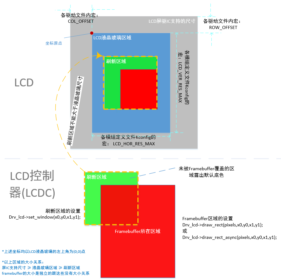
Supports specified drawing area, and this area can arbitrarily intersect with the given output buffer area
Supports frame sync and line sync
Supports synchronous & asynchronous (interrupt mode) data transmission interfaces
LCDC Usage Example 1
Driving ST7789H2 display through 4SPI 1data interface
static LCDC_InitTypeDef lcdc_int_cfg =
{
    .lcd_itf = LCDC_INTF_SPI_DCX_1DATA,     //Choose 4SPI 1data interface
    .freq = 24000000,                       //SPI clock 24MHz
    .color_mode = LCDC_PIXEL_FORMAT_RGB565, //LCDC output color format RGB565
    .cfg = {
        .spi = {

            .dummy_clock = 1,                      //Dummy clock between cmd & data in read mode
            .syn_mode = HAL_LCDC_SYNC_VER,         //TE sychronization mode
            .vsyn_polarity = 0,                    //TE pin polarity
            .vsyn_delay_us = 1000,                 //Delay 1ms to send frame buffer right after received TE signal
            .hsyn_num = 0,                         //Hsyn num if syn_mode is HAL_LCDC_SYNC_VERHOR
        },
    },

};

LCDC_HandleTypeDef hlcdc_st7789h2;

__ROM_USED void LCDC1_IRQHandler(void)
{

    rt_interrupt_enter();

    HAL_LCDC_IRQHandler(lcdc);

    rt_interrupt_leave();
}


void HAL_LCDC_SendLayerDataCpltCbk(LCDC_HandleTypeDef *lcdc)
{
    /*Send layer data completed*/
}

/**
  * @brief  Power on the LCD.
  * @param  None
  * @retval None
  */
void ST7789H2_Init(LCDC_HandleTypeDef *hlcdc)
{
    uint8_t   parameter[14];

    //Initalize interface
    memcpy(&hlcdc->Init, &lcdc_int_cfg, sizeof(LCDC_InitTypeDef));
    HAL_LCDC_Init(hlcdc);

    //Generate a reset pulse to reset ST7789H2
    HAL_LCDC_ResetLCD(hlcdc, LCDC_RESX_NEG_PULSE, 10);

    /************* ST7789H2 initialize sequence start ************************/
    /*Sleep In Command */
    HAL_LCDC_WriteU8Reg(hlcdc, ST7789H2_SLEEP_IN, (uint8_t *)NULL, 0);
    /* Wait for 10ms */
    HAL_Delay(10);

    /* SW Reset Command */
    HAL_LCDC_WriteU8Reg(hlcdc, 0x01, (uint8_t *)NULL, 0);
    /* Wait for 200ms */
    HAL_Delay(200);

    /* Sleep Out Command */
    HAL_LCDC_WriteU8Reg(hlcdc, ST7789H2_SLEEP_OUT, (uint8_t *)NULL, 0);
    /* Wait for 120ms */
    HAL_Delay(120);

    ...
    /************* ST7789H2 initialize sequence end ************************/
}

/**
  * @brief  ST7789H2 read mode should slow down SPI clock to 4MHz
  * @param  enable: false - write spi mode |  true - read spi mode
  * @retval None
  */
void ST7789H2_ReadMode(LCDC_HandleTypeDef *hlcdc, bool enable)
{
    if (HAL_LCDC_IS_SPI_IF(lcdc_int_cfg.lcd_itf))
    {
        if (enable)
        {
            HAL_LCDC_SetFreq(hlcdc, 4000000); //SPI clock is 4MHz on Read mode
        }
        else
        {
            HAL_LCDC_SetFreq(hlcdc, lcdc_int_cfg.freq); //Restore normal frequency
        }

    }
}

/**
  * @brief  Reads the selected LCD Register.
  * @param  RegValue: Address of the register to read
  * @param  ReadSize: Number of bytes to read
  * @retval LCD Register Value.
  */
uint32_t ST7789H2_ReadData(LCDC_HandleTypeDef *hlcdc, uint16_t RegValue, uint8_t ReadSize)
{
    uint32_t rd_data = 0;

    //Entry read mode
    ST7789H2_ReadMode(hlcdc, true);

    HAL_LCDC_ReadU8Reg(hlcdc, RegValue, (uint8_t *)&rd_data, ReadSize);

    //Recovery to normal mode
    ST7789H2_ReadMode(hlcdc, false);

    return rd_data;
}

/**
 * @brief Set LCD & LCDC clip area
 * @param hlcdc LCD controller handle
 * @param Xpos0 - Clip area left coordinate, base on LCD top-left, same as below.
 * @param Ypos0 - Clip area top coordinate
 * @param Xpos1 - Clip area right coordinate
 * @param Ypos1 - Clip area bottom coordinate
 */
void ST7789H2_SetRegion(LCDC_HandleTypeDef *hlcdc, uint16_t Xpos0, uint16_t Ypos0, uint16_t Xpos1, uint16_t Ypos1)
{
    uint8_t   parameter[4];

    //Set LCDC clip area
    HAL_LCDC_SetROIArea(hlcdc, Xpos0, Ypos0, Xpos1, Ypos1);

    //Set LCD clip area
    parameter[0] = (Xpos0) >> 8;
    parameter[1] = (Xpos0) & 0xFF;
    parameter[2] = (Xpos1) >> 8;
    parameter[3] = (Xpos1) & 0xFF;
    HAL_LCDC_WriteU8Reg(hlcdc, ST7789H2_CASET, parameter, 4);

    parameter[0] = (Ypos0) >> 8;
    parameter[1] = (Ypos0) & 0xFF;
    parameter[2] = (Ypos1) >> 8;
    parameter[3] = (Ypos1) & 0xFF;
    HAL_LCDC_WriteU8Reg(hlcdc, ST7789H2_RASET, parameter, 4);
}


/**
 * @brief Send layer data to LCD
 * @param hlcdc LCD controller handle
 * @param RGBCode - Pointer to layer data
 * @param Xpos0 - Layer data left coordinate, base on LCD top-left, same as below.
 * @param Ypos0 - Layer data top coordinate
 * @param Xpos1 - Layer data right coordinate
 * @param Ypos1 - Layer data bottom coordinate
 */
void ST7789H2_WriteMultiplePixels(LCDC_HandleTypeDef *hlcdc, const uint8_t *RGBCode, uint16_t Xpos0, uint16_t Ypos0, uint16_t Xpos1, uint16_t Ypos1)
{
    uint32_t size;

    if ((Xpos0 > Xpos1) || (Ypos0 > Ypos1))
    {
        //Invalid coordinates
        return;
    }

    //Set default layer data
    HAL_LCDC_LayerSetData(hlcdc, HAL_LCDC_LAYER_DEFAULT, (uint8_t *)RGBCode, Xpos0, Ypos0, Xpos1, Ypos1);
    //Write datas to LCD register
    HAL_LCDC_SendLayerData2Reg_IT(hlcdc, 0x2c, 1);
}