UART Example
Source code path: example\rt_device\uart
Supported Platforms
The example can run on the following development boards:
sf32lb52-nano_a128n16
sf32lb52-lcd series
sf32lb56-lcd series
sf32lb58-lcd series
Overview
Under RT-Thread operating system, use RX DMA mode to operate UART2 to verify its serial port transmission and reception capabilities
Note that after development board reset, if uart2 prints log consistent with the image below, it indicates successful transmission. To verify uart2 reception capability, the default serial port print log is used to verify the accuracy of received content
Example Usage
Compilation and Programming
For detailed steps on compilation and downloading, please refer to Getting Started Guide related introduction.
This example uses uart2. When using RT-Thread operating system, uart2 peripheral will be virtualized as an rt_device for read and write operations. At this time, you need to confirm whether the
rtconfig.hfile in the project compilation path contains the following 3 macros:
#define BSP_USING_UART 1
#define BSP_USING_UART2 1
#define BSP_UART2_RX_USING_DMA 1
Only when the above three macros are included, the rt_hw_serial_register function will register the "uart2" rt_device in the rt_hw_usart_init function, and then this device can be successfully found and opened with rt_device_find and rt_device_open.
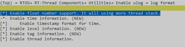
If the above three macros are missing, you need to enable them through the following menuconfig command (Note: missing macros may not cause errors, if configured serial port has no information printed, please check if it’s enabled in time):
sdk.py menuconfig --board=sf32lb52-lcd_n16r8
As shown in the figure below, select uart2 and rx dma, save and exit menuconfig, check if rtconfig.h macro is generated
Switch to example project directory and run scons command to execute compilation:
scons --board=sf32lb52-lcd_n16r8 -j8
Run
build_sf32lb52-lcd_n16r8_hcpu\uart_download.bat, select port as prompted to download:
build_sf32lb52-lcd_n16r8_hcpu\uart_download.bat

Uart Download

please input the serial port num:5
Hardware Connection
Here is the document link, in which the pin definitions have the actual pin mapping relationships: SF32LB52-DevKit-LCD SF32LB52-DevKit-Nano SF32LB56-DevKit-LCD SF32LB58-DevKit-LCD
Board Name |
UART |
TX(Physical Position) |
RX(Physical Position) |
|---|---|---|---|
525/56 |
UART2 |
PAD_PA27(8) |
PAD_PA20(10) |
587 |
UART2 |
PAD_PA28 (CONN2 5) |
PAD_PA29 (CONN2 3) |
52nano |
UART2 |
PAD_PA28 |
PAD_PA25 |
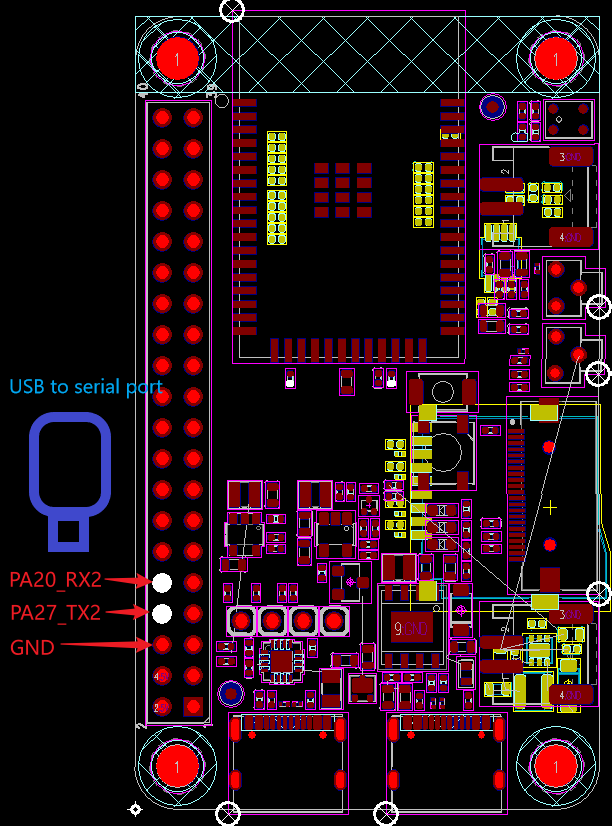
Here is an example diagram of the 525 connection:
PA27 configured in software as UART2 TX, connected to computer USB-to-serial RX
PA20 configured in software as UART2 RX, connected to computer USB-to-serial TX
GND connected to USB-to-serial GND, as shown below:
Example Output Results Display:
Log output: left side shows machine log, right side shows computer USB-to-serial data transmission and reception:
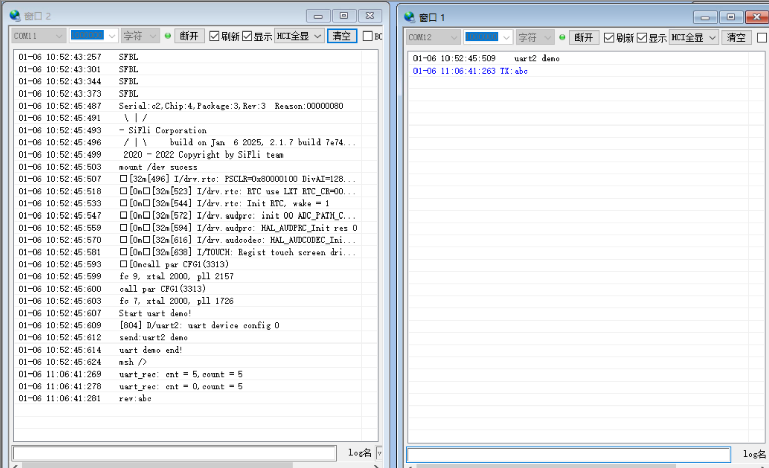
Note: There are two serial ports when serial port is opened, one is the uart2 configured by code for computer USB-to-serial, and one is the built-in debug port uart1
The rev: at the end of the log is the character received from computer USB-to-serial TX
Note: Here the received data is printed using the default serial port instead of uart2, because uart2’s data transmission function is also one of the example features
    SFBL
    Serial:c2,Chip:4,Package:3,Rev:3  Reason:00000080
     \ | /
    - SiFli Corporation
     / | \     build on Oct 23 2024, 2.2.0 build 00000000
     2020 - 2022 Copyright by SiFli team
    mount /dev sucess
    [32m][490] I/drv.rtc: PSCLR=0x80000100 DivAI=128 DivAF=0 B=256
    [0m][32m][517] I/drv.rtc: RTC use LXT RTC_CR=00000001
    [0m][32m][538] I/drv.rtc: Init RTC, wake = 1
    [0m][32m][565] I/drv.audprc: init 00 ADC_PATH_CFG0 0x606
    [0m][32m][587] I/drv.audprc: HAL_AUDPRC_Init res 0
    [0m][32m][609] I/drv.audcodec: HAL_AUDCODEC_Init res 0
    [0m][32m][630] I/TOUCH: Regist touch screen driver, probe=1203a299
    [0mcall par CFG1](35bb)
    fc 9, xtal 2000, pll 2050
    call par CFG1(35bb)
    fc 9, xtal 2000, pll 2051
    Start uart demo!
    [796] D/uart2: uart device config 0
    send:uart2 demo
    uart demo end!
    msh />
    uart_rec: cnt = 5,count = 5
    uart_rec: cnt = 0,count = 5
    rev:abc
Below is the data uart2 demo characters sent by computer USB-to-serial after development board reset, and the data sent manually to verify if uart2 can receive serial port data
    uart2 demo
    TX:abc
Function to verify uart2 reception content accuracy: After sending abc in uart2 log window, it will receive abc characters, line feed, and carriage return in corresponding uart2 interrupt, total 5 character ASCII codes, printing the following content
Note: Always printing one extra log considers that continuous reception may exceed maximum receivable value and require multiple receptions, e.g., if maximum reception is 256 but received is 260, it will print
uart_rec: cnt = 256,count = 256
uart_rec: cnt = 4,count = 260
uart_rec: cnt = 0,count = 260
    uart_rec: cnt = 5,count = 5
    uart_rec: cnt = 0,count = 5
    rev:abc
uart2 Configuration Process
Ensure
rtconfig.hfile contains the following 3 macros: Input command in compilation window to check board=(board type)
#define BSP_USING_UART 1
#define BSP_USING_UART2 1
#define BSP_UART2_RX_USING_DMA 1

sdk.py menuconfig --board=sf32lb52-lcd_n16r8
Set corresponding Uart2 IO ports
   #if defined(BSP_USING_BOARD_EM_LB525XXX)
    HAL_PIN_Set(PAD_PA20, USART2_RXD, PIN_PULLUP, 1);
    HAL_PIN_Set(PAD_PA27, USART2_TXD, PIN_PULLUP, 1);
    #elif defined (BSP_USING_BOARD_EM_LB587XXX)
    HAL_PIN_Set(PAD_PA29, USART2_RXD, PIN_PULLUP, 1);
    HAL_PIN_Set(PAD_PA28, USART2_TXD, PIN_PULLUP, 1);
    #endif
Note:
Except for 55x chips, can be configured to any IO with PA*_I2C_UART functionality to output UART2 waveform (to query pin multiplexing table, search in project path files such as: bf0_pin_const.c)
HAL_PIN_Set last parameter is for hcpu/lcpu selection, 1: select hcpu, 0: select lcpu
Hcpu PA ports cannot be configured for Lcpu uart peripherals, such as uart5, uart6 output
Explanation of partial content in serial port initialization function int uart2_init(void):
Usert_device_find,rt_device_control,rt_device_opensequentially to find, configure, and openuart2device
#define UART_DEMO_NAME "uart2"

    /* 2, find  and config uart2 device */
    g_uart_device = rt_device_find(UART_DEMO_NAME);
    if (!g_uart_device)
    {
        LOG_E("find %s failed!\n", UART_DEMO_NAME);
        return RT_ERROR;
    }

    /* config uart2 baud_rate */
    {
        rt_err_t err;
        struct serial_configure config = RT_SERIAL_CONFIG_DEFAULT;
        config.baud_rate = 1000000; /* Configure uart2 baud rate to 1000000 */
        err = rt_device_control(g_uart_device, RT_DEVICE_CTRL_CONFIG, &config);
        LOG_D("uart device config %d", err);
    }

    /* Initialize rx_sem semaphore, released in uart_rx_ind function, used in serial_rx_thread_entry thread */
    rt_sem_init(&rx_sem, "rx_sem", 0, RT_IPC_FLAG_FIFO);

	/* Configure uart2 to use rx dma mode for reception */
	rt_err_t open_result = rt_device_open(g_uart_device, RT_DEVICE_OFLAG_RDWR | RT_DEVICE_FLAG_DMA_RX);
	//using interring mode when DMA mode not supported
	if (open_result == -RT_EIO)
	{
	    rt_device_open(g_uart_device, RT_DEVICE_OFLAG_RDWR | RT_DEVICE_FLAG_INT_RX);/* Configure uart2 interrupt */
    }
    /* set the callback function of recieving */
Configure uart2 interrupt callback function
uart_rx_ind, and create and start threadserial_rx_thread_entryto receive and process data received by RX DMA
    /* Set uart_rx_ind as uart2 interrupt callback function */
    rt_device_set_rx_indicate(g_uart_device, uart_rx_ind);

    /* creat the thread of g_uart_device */
    rt_thread_t thread = rt_thread_create("g_uart_device", serial_rx_thread_entry, RT_NULL,  3 * 1024, 12, 10);

    /* start the thread of g_uart_device */
    if (thread != RT_NULL)
    {
        rt_thread_startup(thread);
    }
    else
    {
        ret = RT_ERROR;
    }
static void serial_rx_thread_entry(void parameter) receives and processes data received by RX DMA: uses default serial port print function
rt_kprintfto verify data received by uart2, continuously loops usingcnt = rt_device_read()to check if data is currently received, so log printing will always print one extra case when cnt=0
uint16_t count = 0;
    uint8_t cnt = 0;

    while (1)
    {
        rt_sem_take(&rx_sem, RT_WAITING_FOREVER);
        while (1)
        {
            cnt = rt_device_read(g_uart_device, -1, &data[count], ONE_DATA_MAXLEN);
            count += cnt;
            rt_kprintf("uart_rec: cnt = %d,count = %d\n", cnt, count);
            if (0 == cnt) break;
        }
        rt_kprintf("rev:");
        for (uint16_t i = 0; i < count; i++)
        {
            rt_kprintf("%c", data[i]);
        }
        count = 0;
        rt_kprintf("\n");
    }
uart2 sends data through uart_send_data function
    uint8_t tx_data[ONE_DATA_MAXLEN] = {'u','a','r','t','2',' ','d','e','m','o','\n'};
    uart_send_data(tx_data,12);
After enabling
finshfunctionality, you can inputlist_devicein log serial terminal to check ifuart2is in open status. 0 means device is registered, 1,2 means number of times device is opened
 TX:list_device
   list_device
   device           type         ref count
   -------- -------------------- ----------
   audcodec Sound Device         0
   audprc   Sound Device         0
   rtc      RTC                  0
   pwm3     Miscellaneous Device 0
   touch    Graphic Device       0
   lcdlight Character Device     0
   lcd      Graphic Device       0
   i2c4     I2C Bus              0
   i2c1     I2C Bus              0
   lptim1   Timer Device         0
   btim1    Timer Device         0
   uart2    Character Device     1
   uart1    Character Device     2
   pin      Miscellaneous Device 0
   msh />
This only demonstrates one recommended usage of uart. For other operations under rt-thread operating system, refer to rt-thread official website user manual
Exception Diagnosis
No uart2 waveform output
Use
pin status 20/27command to check corresponding PA20, PA27 IO status FUNC. VAL level should be 1
    msh />
 TX:pin status 20
    pin status 20
    [I/TEST.GPIO] PIN 20, FUNC=4, VAL=1, DIG_IO_PU, GPIO_MODE_INPUT, irqhdr=/, arg=/
    msh />
    msh />
 TX:pin status 27
    pin status 27
    [I/TEST.GPIO] PIN 27, FUNC=4, VAL=1, DIG_IO_PU, GPIO_MODE_INPUT, irqhdr=/, arg=/
    msh />
    msh />
Use
list_devicecommand to check ifuart2device exists and is openedCheck if uart2 configuration process is all effective
uart2 waveform normal, computer serial port cannot receive data
Check if uart2 output and computer serial port connection are normal, need TX to connect RX, RX to connect TX, if baud rate is consistent, and if corresponding TX, RX pins are correct
Check hardware connection, including if uart2 output level and computer uart level are consistent
Computer serial port sends data, uart2 has data reception loss phenomenon
Confirm if serial port DMA buffer length is sufficient
#define RT_SERIAL_RB_BUFSZ 256
/*
&data[count]: memory address for received data;
ONE_DATA_MAXLEN: prepared reception length, can be larger than DMA buffer length;
Return value: actual received length, 0 means reception completed;
*/
rt_device_read(g_uart_device, -1, &data[count], ONE_DATA_MAXLEN);
Reference Documents
EH-SF32LB52X_Pin_config_V1.3.0_20231110.xlsx
DS0052-SF32LB52x-芯片技术规格书 V0p3.pdf
DS0058-SF32LB58x-芯片技术规格书 V1p8.pdf
RT-Thread Official Website https://www.rt-thread.org/document/site/#/rt-thread-version/rt-thread-standard/README
Update Log
Version |
Date |
Release Notes |
|---|---|---|
0.0.1 |
10/2024 |
Initial version |
0.0.2 |
12/2024 |
2.0 |