Using SPI to Read TF Card ID Through CMD Instructions
Source code path: example\rt_device\spi
Supported Platforms
sf32lb52-lcd_n16r8
Overview
Under RT-Thread operating system, demonstrate reading TF card ID by sending CMD instructions through SPI interface
Example Usage
Compilation and Programming
Using sf32lb52-lcd_n16r8 as Example
This example uses spi1. When using RT-Thread operating system, spi1 peripheral will be virtualized as an rt_device for read and write operations. At this time, you need to confirm whether the
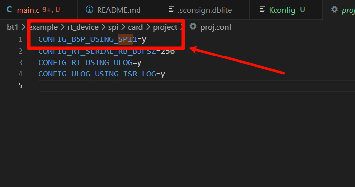
rtconfig.hfile in the path contains the following 2 macros:
#define BSP_USING_SPI 1
#define BSP_USING_SPI1 1
Only when the above two macros are included, the rt_hw_spi_device_attach function will create the spi1 rt_device in the rt_spi_msd_init function. Only after the device is created can rt_device_find and rt_device_open succeed later.
If the above macros are missing or not enabled, they can be enabled through the menuconfig menu with the following operations:
sdk.py menuconfig --board=sf32lb52-lcd_n16r8
As shown in the figure below, select SPI1 enable (DMA is needed, select corresponding DMA option), save and exit menuconfig, check if rtconfig.h macro is generated
Switch to project example directory and run scons command for code compilation:
scons --board=sf32lb52-lcd_n16r8 -j8
Switch to example
project/build_xxdirectory and runuart_download.bat, select port as prompted to download:
build_sf32lb52-lcd_n16r8_hcpu\uart_download.bat//Download code
Uart Download
please input the serial port num:5
For detailed steps on compilation and downloading, please refer to Getting Started Guide related introduction.
Hardware Connection
Development Board |
Function Pin |
Local Device Pin |
Remote Device Pin |
Physical Pin (CONN2) |
|---|---|---|---|---|
sf32lb52-lcd |
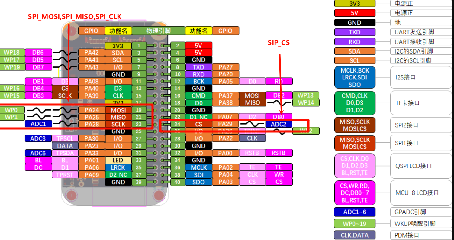
PA_24 |
dio |
SPI_MOSI |
19 |
PA_25 |
di |
SPI_MISO |
21 |
|
PA_28 |
clk |
SPI_CLK |
23 |
|
PA_29 |
cs |
SPI_CS |
24 |
Note that function pins and device pins do not have a one-to-one correspondence. Please refer to schematic for device pins
Example Output Results Display
 Log print results for successful or failed ID reading are as follows
If no TF card is inserted or reading fails, log prints:
[err]SD card goto IDLE mode timeout
[SD]msd init failed,spi_dev=xxxxxxxx
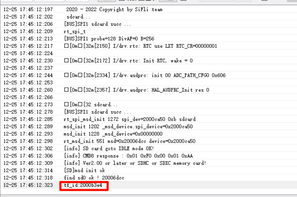
If ID reading is successful, log prints:
 [SD] msd init ok
 find sd0 ok!
 tf_id:2000b3e4(last four digits are TF card ID in hex)
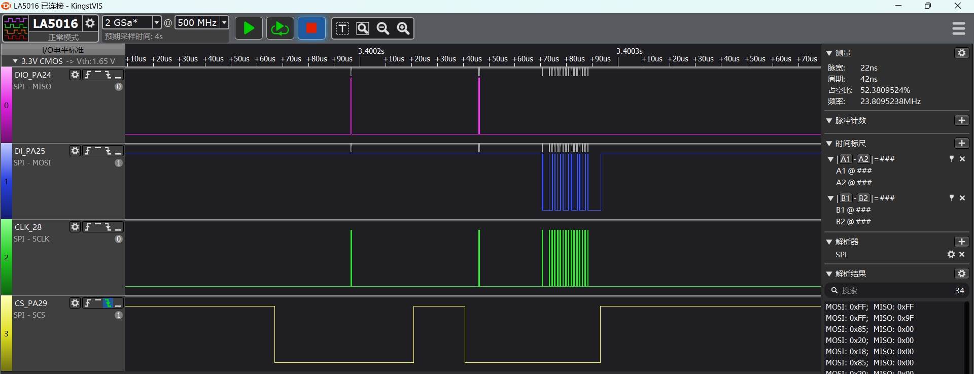
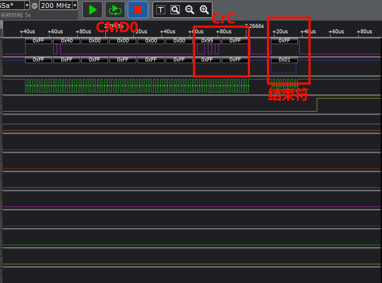
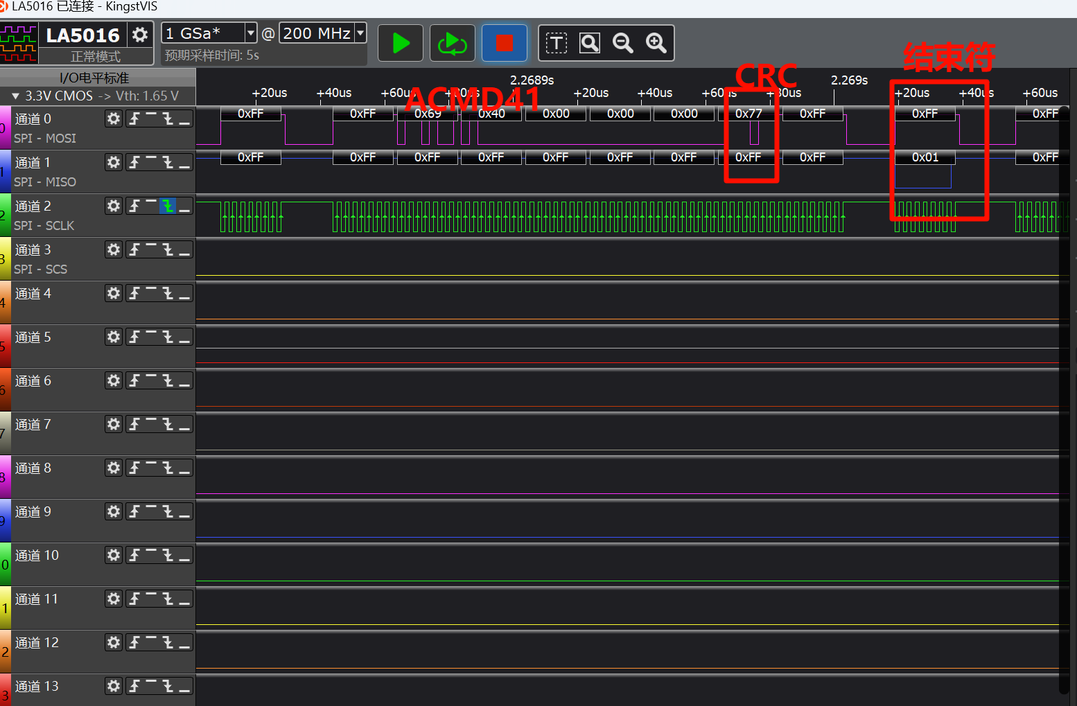
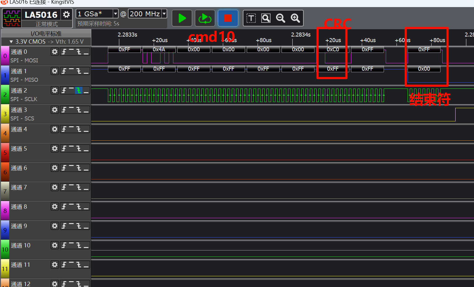
The figure below shows captured waveforms of sending CMD instructions
CMD0 waveform (send CMD0 to set device to SPI mode)
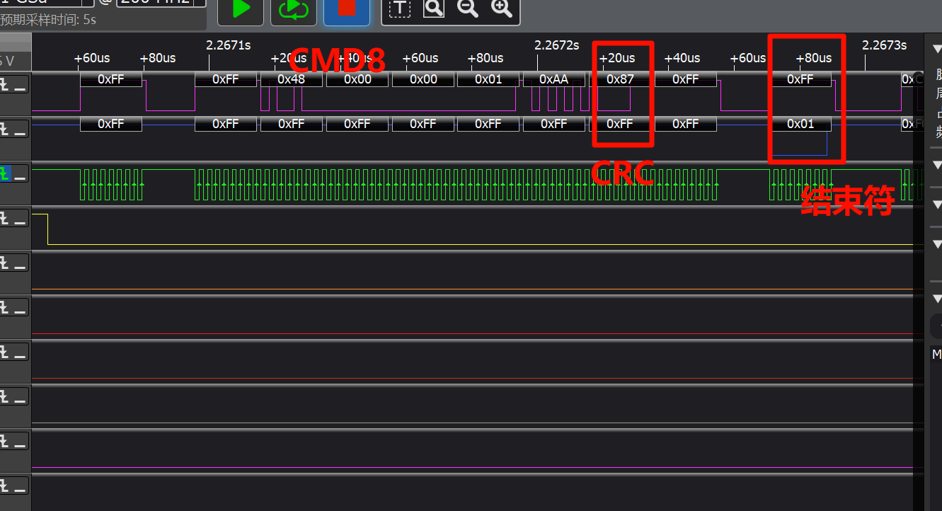
 CMD8 waveform (verify if card protocol is SD2.0)
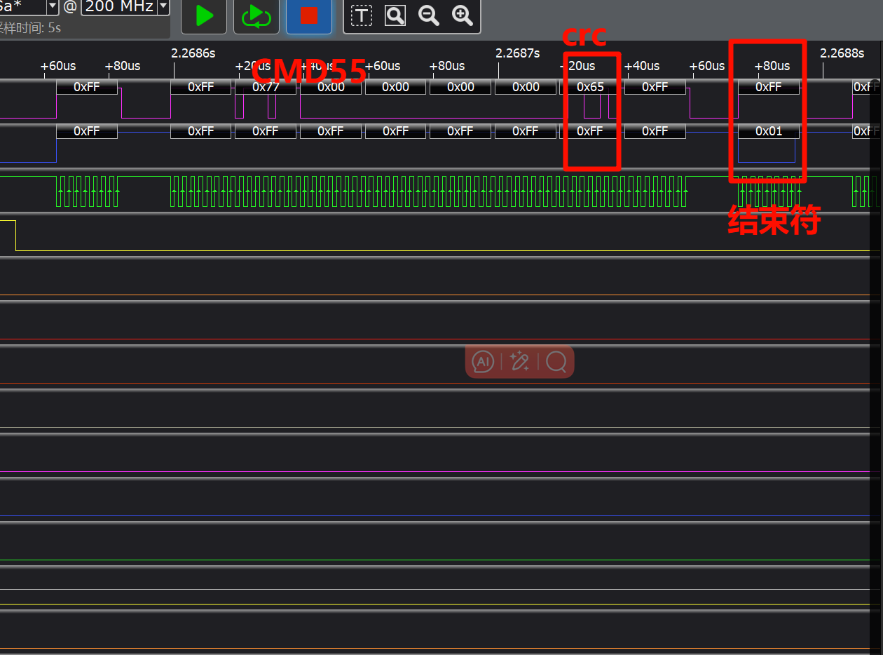
 CMD55 waveform (special instruction prefix command, needs to be sent before sending ACMD class instructions)
 ACMD41 waveform (get SD voltage value, test current SD card support protocol, check if required voltage value is normal)
 CMD10 waveform (read CID information)
 Note
Note
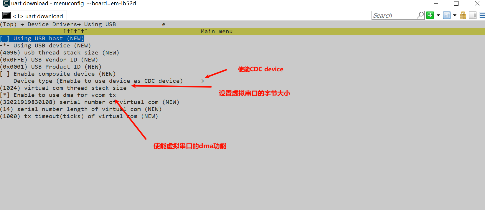
If using TX DMA, you need to enable
#define BSP_SPI1_TX_USING_DMA 1;When SPI data volume is small, using DMA increases code overhead and actually reduces real-time performance;
Using sf32lb52-lcd_52d development board as example, configure corresponding spi1 IO ports
    /* 1, pinmux set to spi1 mode */
    HAL_PIN_Set(PAD_PA24, SPI1_DIO, PIN_PULLDOWN, 1);       // SPI1 (Nor flash)
    HAL_PIN_Set(PAD_PA25, SPI1_DI,  PIN_PULLUP, 1);
    HAL_PIN_Set(PAD_PA28, SPI1_CLK, PIN_NOPULL, 1);
    HAL_PIN_Set(PAD_PA29, SPI1_CS,  PIN_NOPULL, 1);
Note
CLK and CS are output ports, no need to configure pull-up/pull-down state
DIO and DI ports are input ports, need to configure pull-up/pull-down. If peripheral has no special requirements, use these default values
HAL_PIN_Set last parameter is for hcpu/lcpu selection, 1: select hcpu, 0: select lcpu
Hcpu PA ports cannot be configured for Lcpu spi peripherals, such as spi3, spi4 output
Use
rt_device_find,rt_device_control,rt_device_opensequentially to find, configure, and openspidevice
rt-thread defines multiple devices to adapt different devices using the same spi bus. Need to attach
spi1device to this device through rt_hw_spi_device_attach, here it’stfcord
Workflow
Use rt_spi_msd_init() function for SPI device registration
Use msd_init() function for device initialization and mount tfcord device on sd device
Use rt_msd_init() function for device conversion and spi parameter configuration, send a series of CMD instructions to initialize TF card and read data from its cid register to get its ID
Exception Diagnosis
No spi1 waveform output
Use
pin status 24/25/28/29command to check corresponding PA24, PA25, PA28, PA29 IO status FUNC. PA29 as CS pin should be high level, corresponding VAL=1
    msh />
 TX:pin status 24
    pin status 24
    [32m[109951461] I/TEST.GPIO: PIN 24, FUNC=2, VAL=0, DIG_IO_PD, GPIO_MODE_INPUT, irqhdr=/, arg=/
    [0mmsh />
    msh />
 TX:pin status 25
    pin status 25
    [32m[110036013] I/TEST.GPIO: PIN 25, FUNC=2, VAL=1, DIG_IO_PU, GPIO_MODE_INPUT, irqhdr=/, arg=/
    [0mmsh />
    msh />
 TX:pin status 28
    pin status 28
    [32m[110115999] I/TEST.GPIO: PIN 28, FUNC=2, VAL=0, DIG_IO, GPIO_MODE_INPUT, irqhdr=/, arg=/
    [0mmsh />
    msh />
 TX:pin status 29
    pin status 29
    [32m[110195531] I/TEST.GPIO: PIN 29, FUNC=2, VAL=1, DIG_IO, GPIO_MODE_INPUT, irqhdr=/, arg=/
    [0mmsh />
    msh />
Use
list_devicecommand to check ifspi1,nor_flashdevices exist and are openedCheck if spi1 initialization and configuration process are all effective
spi1 waveform normal, spi1 DI cannot receive data
First use oscilloscope to check if waveform level is normal
Use logic analyzer to capture timing, compare with peripheral specification to see if waveform requirements are consistent
Check if spi1 output and peripheral connection are normal
Check if peripheral power supply is normal
spi waveform timing is insufficient
As shown in the figure, cs signal to clk actual data has excessive delay in between, this is due to delay caused by rt-thread encapsulation. If high timing requirements exist, refer to direct HAL operation examples