GPIO Power Consumption Test Example
Source code path: example/pm/gpio
Supported Development Boards
This example can run on the following development boards:
sf32lb52-core_n16r16
Overview
Under the RT-Thread operating system, this is a power consumption test that uses a timer to wake up and read GPIO. The LCPU has entered sleep state, and the HCPU has entered low power state (HCPU frequency is 48MHz). The program wakes up and reads GPIO once every 100ms.
Hardware Connection
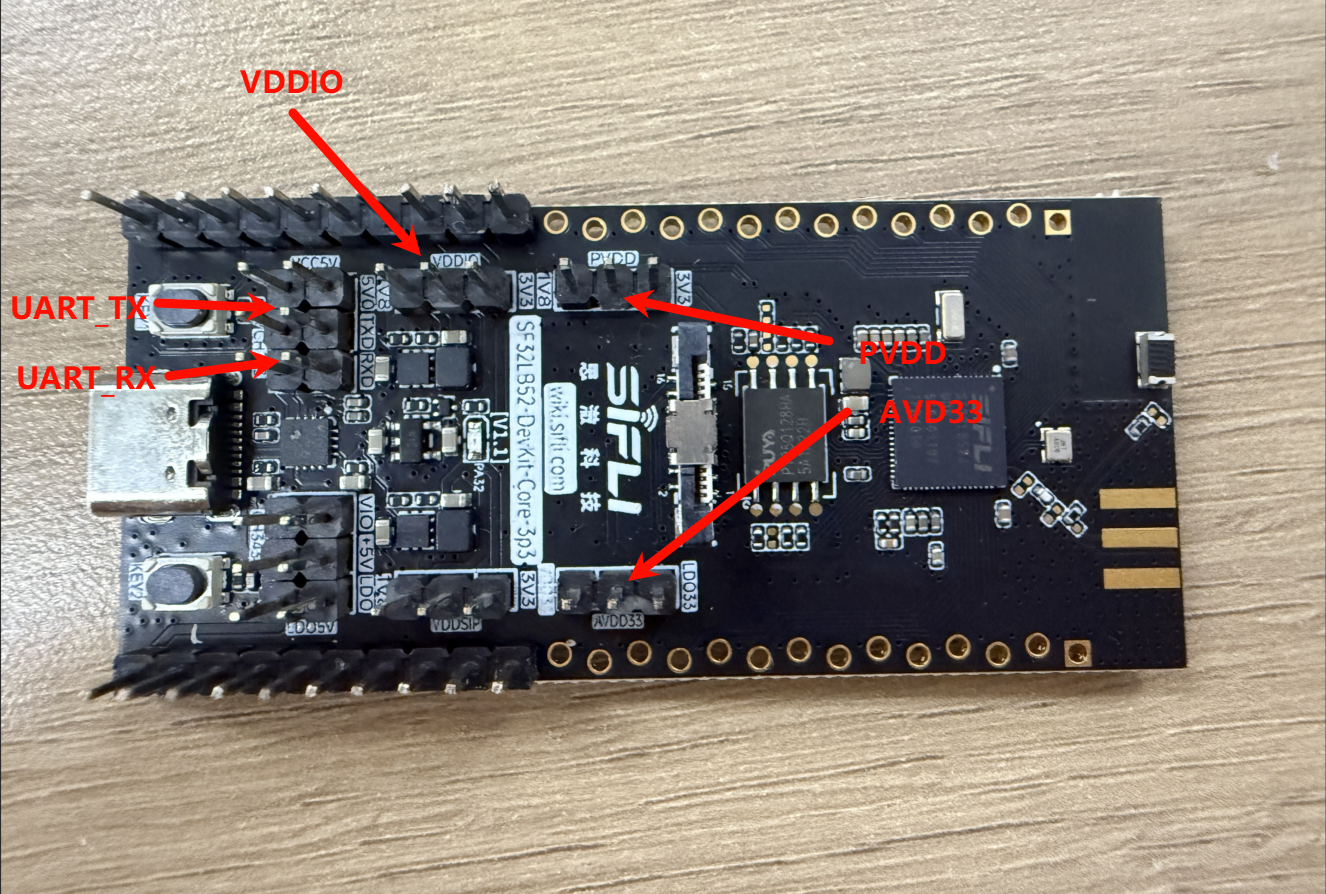
During low power consumption testing, the board is no longer powered through USB, but needs to be powered through a power consumption detection tool via UDDIO, PVDD, and AVDD to the development board. Therefore, the following operations need to be performed to conduct power consumption testing.
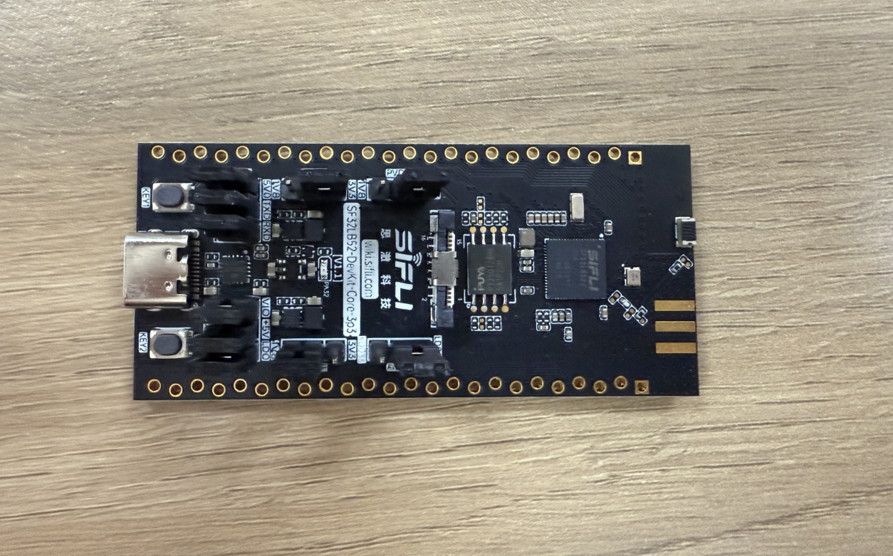
Original power supply situation of the development board
First, remove all jumper caps
Connect UDDIO, PVDD, and AVDD to the power pins on the PPK respectively, and connect GND to the PPK’s GND pin
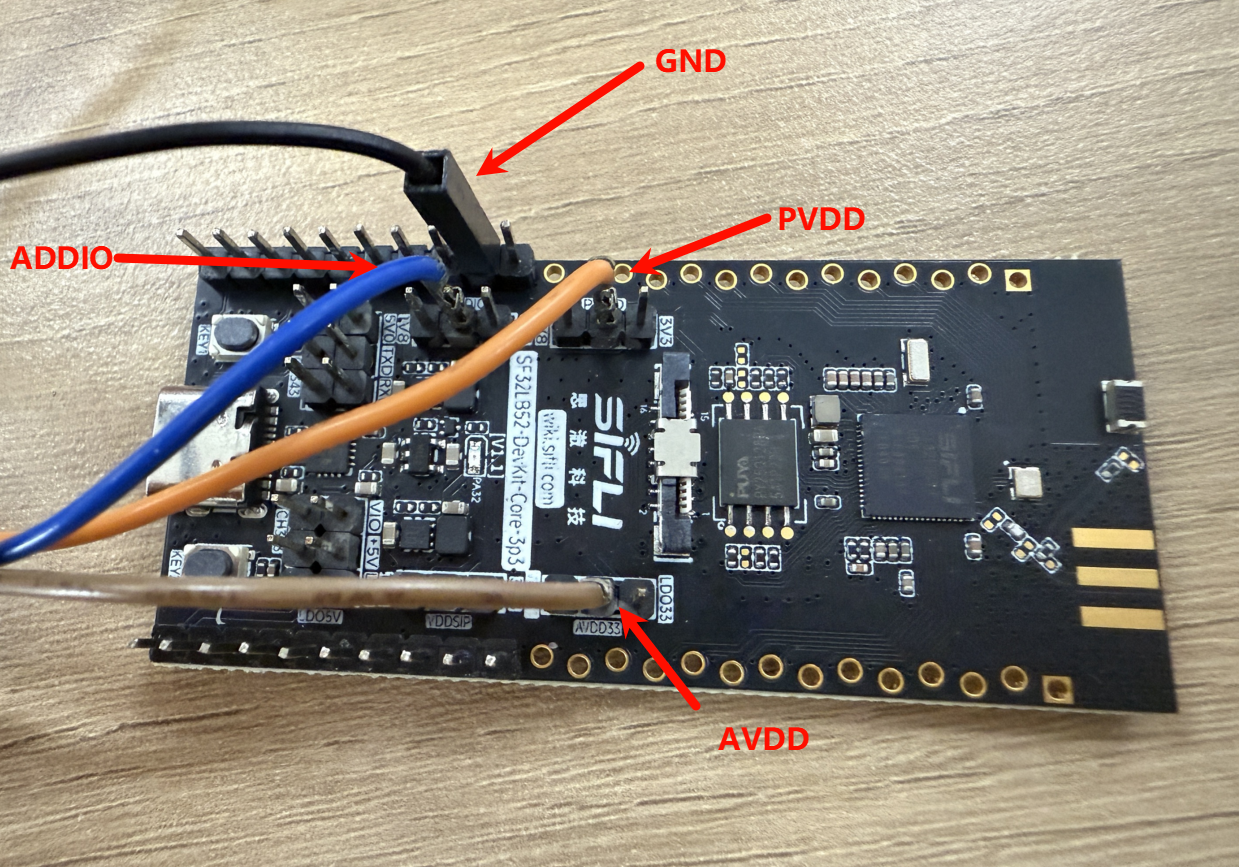
For convenient debugging, a UART converter can be connected to the board’s TX and RX
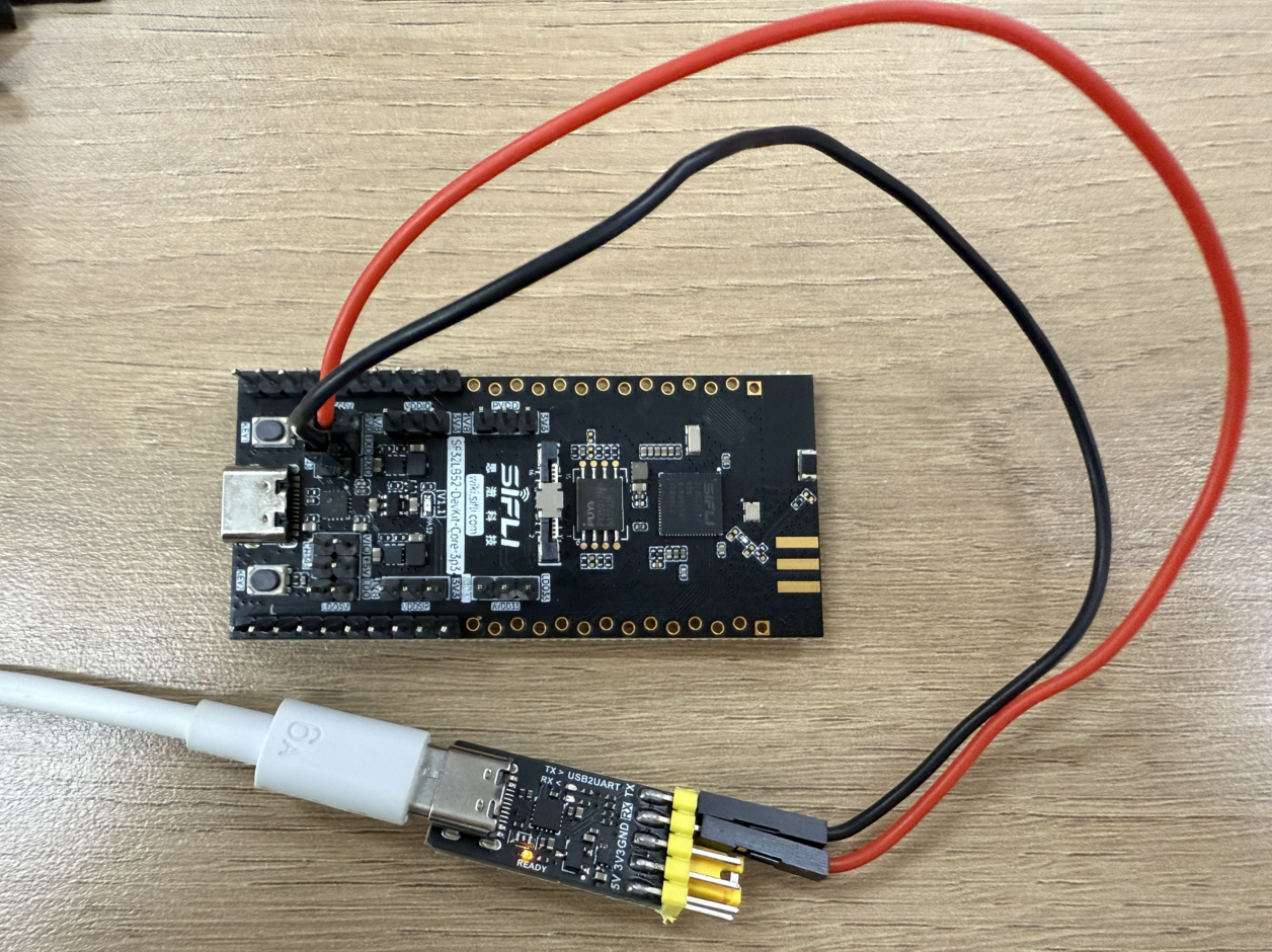
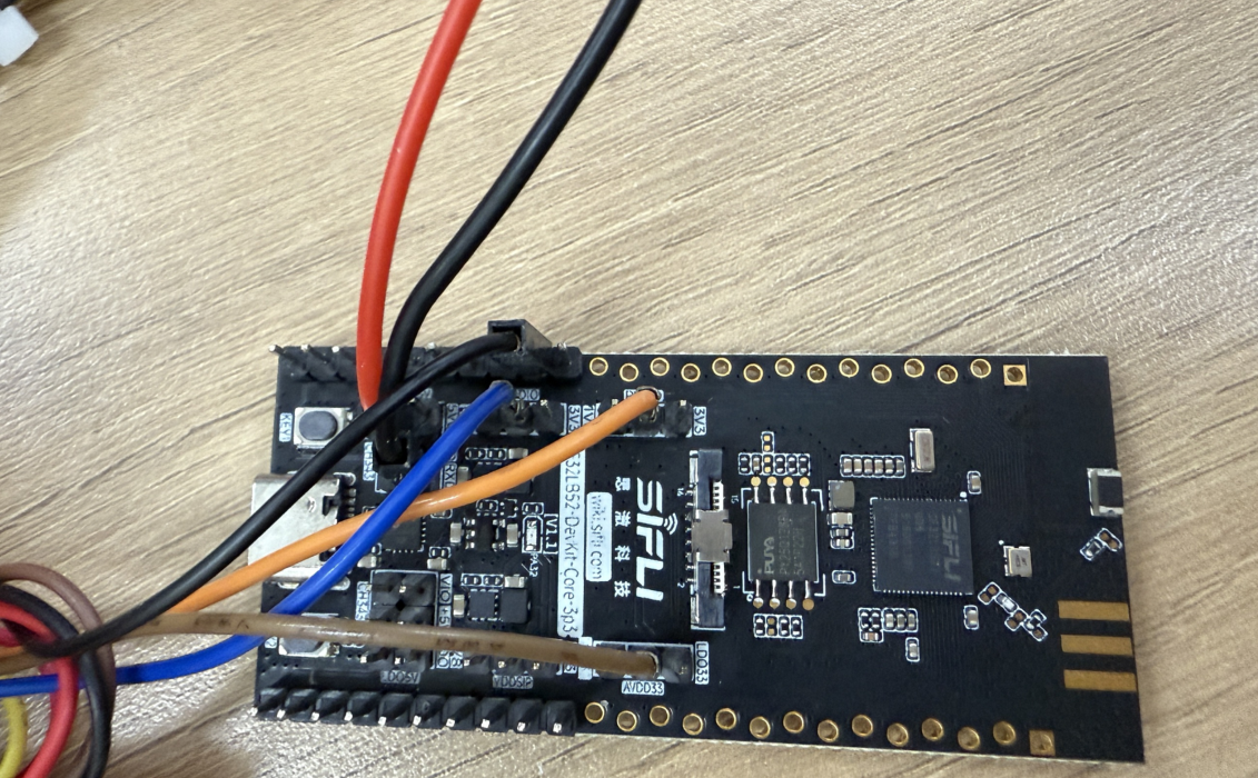
Final wiring
Power Consumption Test Results
Big Core Frequency (MHz) |
Average Current (uA) |
Average Wake-up Current (mA) |
Sleep State Base Current (uA) |
IO Read (mA) (including base current) |
|---|---|---|---|---|
48 |
32.62 |
1.25 |
15.33 |
2.44 |
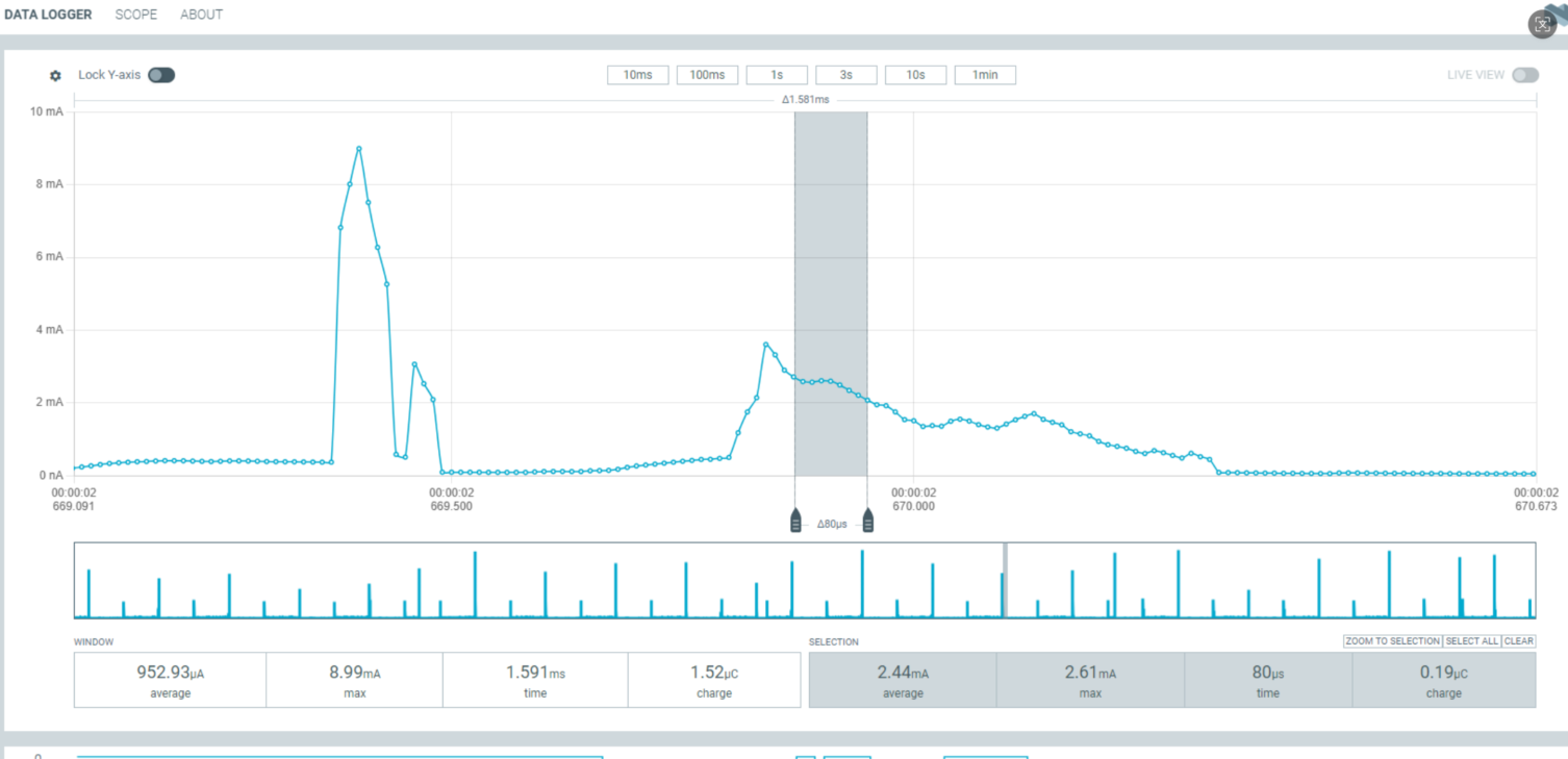
The test results show that at 48MHz, the IO read current is 2.44mA, the average wake-up current is 1.25mA, and the sleep state base current is 15.33uA. Detailed data is shown below:
Average wake-up current is 1.25mA
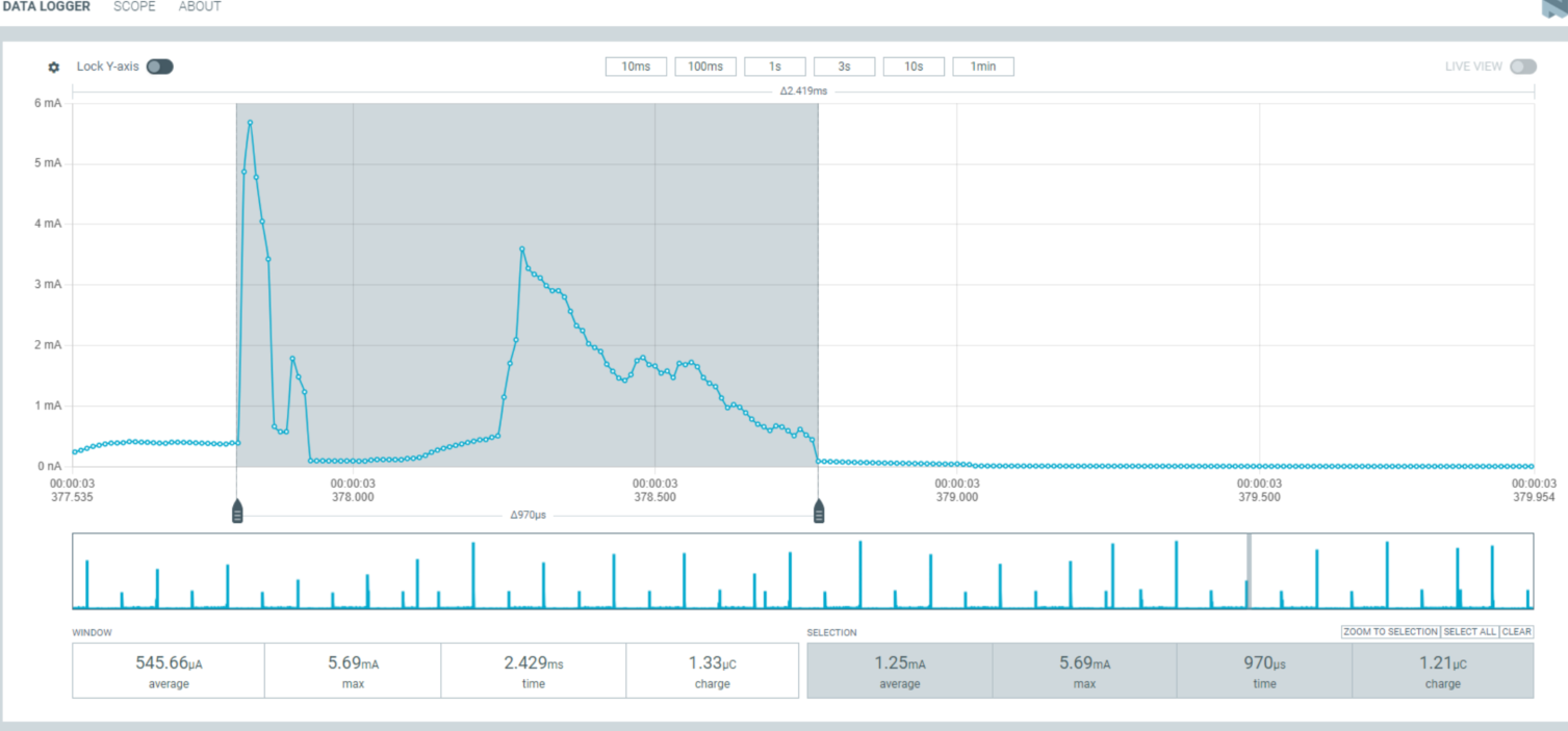
Sleep state base current is 15.33uA

IO read current is 2.44mA
Abnormal Diagnosis
If the measured results differ significantly from the documentation, there may be abnormalities. Please conduct troubleshooting on your own. UDDIO: Chip IO power supply PVDD: Chip main power input AVDD: Chip audio
If there are hardware modifications, it may cause significant deviations in test results
Insufficient power supply will also cause significant deviations in test results (using 3.3V power supply), and may even cause chip burnout
Troubleshooting steps: The above three power supplies can be powered individually using a power consumption testing tool, and the other two routes can be powered through external VCC. This allows for single-path power consumption testing to identify which power supply has abnormalities.