Application Startup Flow
SF32LB52X is a dual-core chip with multiple on-chip and off-chip memory interfaces. MPI1 is the on-chip memory interface and can connect PSRAM and NOR Flash. MPI2 and SDMMC are off-chip; MPI2 can connect NOR/PSRAM/NAND, and SDMMC can connect SD-NAND or SD-eMMC. The application runs on the big core. The Bluetooth Controller stack runs on the small core, which is not open to users. The small core is started by the Bluetooth Host stack on the big core; users do not need to care about it.
The application startup on the big core consists of three stages:
First‑stage Bootloader: Burned in the SF32LB52X internal ROM; loads the second‑stage bootloader from Flash to RAM and jumps to run it
Second‑stage Bootloader: Loads the application from Flash and jumps to execute it
Application: User program
First‑stage Bootloader
The first‑stage bootloader is burned in the chip ROM with the interrupt vector table address at 0. After power‑on, the first‑stage bootloader runs first. Depending on the package type, it determines the location of the Flash partition table (internal or external Flash, referred to as the boot Flash below; Flash includes NOR, NAND, SD and eMMC). According to the second‑stage bootloader address indicated by the partition table (must be on the boot Flash), it copies the second‑stage bootloader code to RAM and jumps to run it.
During the first‑stage bootloader, the big core runs at the default clock frequency after power‑up and initializes the boot Flash IO configuration. For the numeric series, both cold boot and hibernate resumes wait for 2 seconds at the first‑stage boot; for the letter series, only cold boot waits 2 seconds.
For numeric‑series chips, VDD33_LDO2 (corresponding to the chip’s VDD33_VOUT1 output) is turned on during the first‑stage bootloader. For letter‑series chips, PA21 is driven high during the first‑stage bootloader.
Warning
If booting from NOR Flash, make sure the Flash device is in 3‑byte address mode (for devices larger than 16 MB, normal operation may set 4‑byte address mode to access the full address space), otherwise the first‑stage bootloader cannot correctly read from Flash. For the numeric series, calling HAL_PMU_Reboot to reboot or HAL_PMU_EnterHibernate to power off will automatically turn off VDD33_LDO2, so on the next power‑up the device returns to the default 3‑byte address mode.
Second‑stage Bootloader
The second‑stage bootloader loads the application and jumps to execute it according to the package type and the Flash partition table. Depending on the package type, applications support the following boot modes. Execution modes include XIP (execute directly at a NOR Flash address; code storage address equals execution address) and non‑XIP (copy code from Flash into RAM for execution; the storage address differs from the execution address). Regardless of boot mode, the application and the second‑stage bootloader reside on the same boot Flash; the difference is only how the application code executes:
On‑chip NOR Flash (MPI1): Boot Flash is on‑chip NOR; the application is stored on on‑chip NOR and runs in XIP mode
No on‑chip NOR Flash:
External NOR Flash (MPI2): Boot Flash is external NOR; the application is stored on external NOR and runs in XIP mode
On‑chip PSRAM (MPI1), external NAND Flash (MPI2): Boot Flash is external NAND; the application is stored on external NAND and runs in non‑XIP mode, i.e., code is copied to on‑chip PSRAM for execution
On‑chip PSRAM, external SD Flash (SDIO): Same as item 2.
For packages with on‑chip PSRAM, the 52 numeric series turns on LDO1V8 and initializes PSRAM in the second‑stage bootloader. For letter series, whether to use LDO1V8 to power PSRAM depends on the board configuration.
The second‑stage bootloader adjusts clock settings; the modified configuration is shown below:
Module |
Clock Source |
Frequency (MHz) |
|---|---|---|
DLL1 |
/ |
144 MHz |
DLL2 |
/ |
288 MHz |
Big‑core system clock |
DLL1 |
144 MHz |
On‑chip NOR Flash |
System clock |
48 MHz |
On‑chip PSRAM |
DLL2 |
144 MHz |
External Flash |
DLL2 |
48 MHz |
External SD |
DLL2 |
The second‑stage bootloader does not load PMU calibration parameters; it only modifies the IO settings related to the storage being used. Cache is disabled, and MPU is disabled.
Module |
Setting |
|---|---|
PMU |
Default |
MPU |
Disabled |
Cache |
Disabled |
Application
ResetHandler
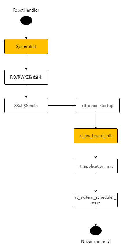
The application entry function is ResetHandler (in drivers\cmsis\sf32lb52x\Templates\arm\startup_bf0_hcpu.S). Its flow is shown below. The user main function is called by the main thread created in rt_application_init. See main_thread_entry flow.
SystemInit
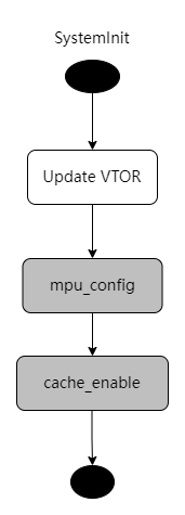
SystemInit (in drivers/cmsis/sf32lb52x/Templates/system_bf0_ap.c) runs before variable initialization (therefore do not use variables with initial values during this period, and avoid relying on the zero‑initialized section being 0). It updates the VTOR register to redirect the interrupt vector table, and calls mpu_config and cache_enable to initialize the MPU and enable Cache. These two functions are weak symbols, so applications can override them.
rt_hw_board_init
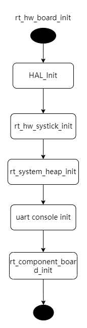
rt_hw_board_init performs low‑level hardware initialization such as clock and IO configuration, PSRAM and NOR Flash initialization, heap and serial console initialization. rt_components_board_init is an application‑defined initialization hook and calls different functions depending on the application configuration.
HAL_Init
HAL_Init completes HAL initialization: it loads PMU calibration parameters, updates clock and IO settings, and initializes PSRAM and NOR Flash (according to the new clock configuration). In the diagram, green functions are board‑level driver functions with board‑specific implementations (HAL_PreInit, BSP_IO_Init, BSP_PIN_Init, BSP_Power_Up, etc.). Gray functions are virtual hooks implemented by the application (or not), independent of the board, so different applications on the same board can customize behavior (e.g., different IO configurations). Horizontally, the flow shows nested calls inside functions (e.g., HAL_PreInit calls clock‑configuration helpers; HAL_MspInit calls BSP_IO_Init). Vertically, it shows serially executed functions (e.g., after HAL_PreInit finishes, HAL_PostMspInit runs).
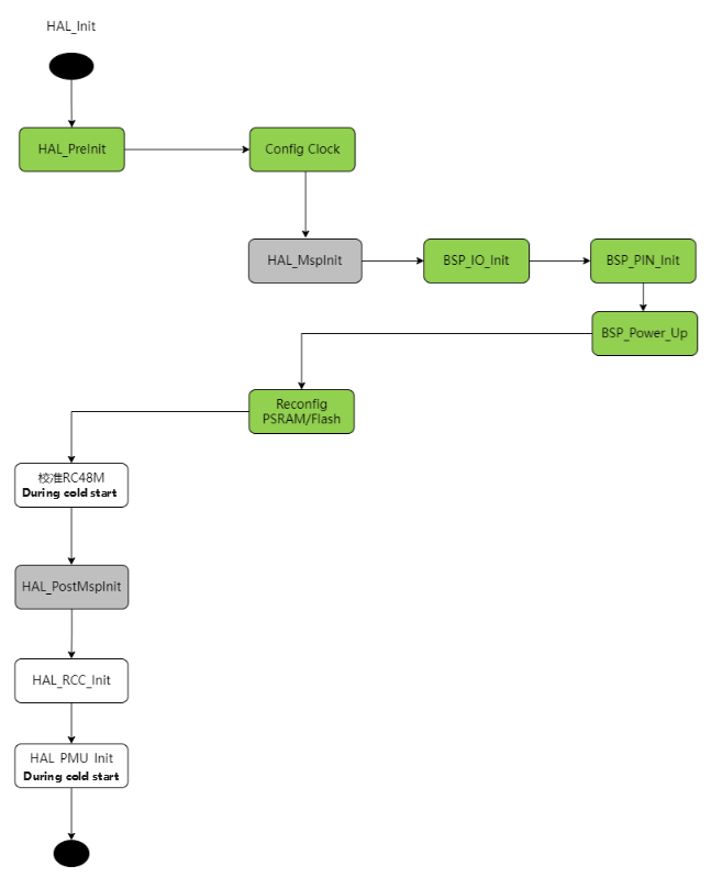
Config Clock adjusts:
Load PMU calibration values
Start GTimer
Switch PMU to RC32K
If external XT32K is used, switch RTC to XT32K
Set system clock to 240 MHz (DLL1)
Set DLL2 to 288 MHz (same as the second‑stage bootloader)
Loaded PMU calibration registers include:
BUCK_CR1_BG_BUF_VOS_POLAR
BUCK_CR1_BG_BUF_VOS_TRIM
LPSYS_VOUT_VOUT
VRET_CR_TRIM
PERI_LDO_LDO18_VREF_SEL
PERI_LDO_LDO33_LDO2_SET_VOUT
PERI_LDO_LDO33_LDO3_SET_VOUT
AON_BG_BUF_VOS_POLAR
AON_BG_BUF_VOS_TRIM
HXT_CR1_CBANK_SEL (added in Xiaomi branch; previously loaded in the rt_component_board_init stage). The calibration‑loading code may run from Flash or PSRAM.
The details of the PMU parameters initialized by HAL_PMU_Init can be found in the HAL_PMU_Init function in drivers/hal/bf0_hal_pmu.c.
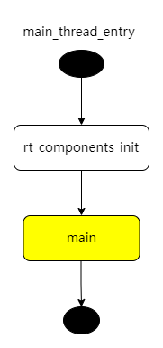
rt_application_init
rt_application_init creates the main thread with entry main_thread_entry. After thread scheduling is enabled (i.e., after rt_system_scheduler_start), the main thread is scheduled and enters main_thread_entry, first calling rt_components_init to initialize components, then calling main (implemented by the application). User code starts from main. For example, the rt_driver sample’s main function is in example/rt_driver/src/main.c.
Board‑level Driver Interfaces
Each board needs to implement the following board‑level driver functions. Refer to files under customer/boards/eh-lb52xu.
Function |
Required |
Description |
|---|---|---|
HAL_PreInit |
YES |
Recommend referencing a board with similar hardware form |
BSP_Power_Up |
NO |
Called after cold boot and wake‑up |
BSP_IO_Power_Down |
NO |
Called before sleep |
BSP_LCD_Reset |
NO |
|
BSP_LCD_PowerUp |
NO |
Called when powering the display on |
BSP_LCD_PowerDown |
NO |
Called when powering the display off |
BSP_TP_Reset |
NO |
|
BSP_TP_PowerUp |
NO |
Called when powering touch on |
BSP_TP_PowerDown |
NO |
Called when powering touch off |
HAL_MspInit |
NO |
Called by |
HAL_PostMspInit |
NO |
|
BSP_IO_Init |
NO |
Called by |
BSP_PIN_Init |
NO |
Called by |
Application‑defined Driver Interfaces
If different applications on the same board need different HAL_MspInit behavior, you can implement HAL_MspInit under the application directory; otherwise, it can reside under the board directory.
Function |
Required |
Description |
|---|---|---|
HAL_MspInit |
NO |
|
HAL_PostMspInit |
NO |