Impeller
1 Overview
Impeller is an in-house tool developed by SiFli Technology, designed for production-line use. It supports both UART and JLink SWD interfaces and provides firmware flashing, flash erasing, 48 MHz crystal and battery measurement calibration, and PCBA testing. Up to 16 devices of the same type can be processed in parallel.
Tool path: tools/Impeller
2 Environment Setup
Impeller requires no installation and runs directly on Windows (XP / 7 / 10 / 11 …).
When using the SWD interface, JLink hardware and its companion software are required. The recommended steps are:
Purchase an official JLink device and install the SEGGER JLink Windows driver software. The version used during development of this tool is V680a. It is recommended to install the software at the default path
C:\Program Files (x86)\SEGGER.After installing the SEGGER software, configure its path in the tool’s configuration file
Impeller.ini. e.g.:[COMMON_SET]→JLINK_PATH=C:\Program Files (x86)\SEGGER\JLinkCopy the SiFli JLink programming driver files to the JLink installation directory (default:
C:\Program Files (x86)\SEGGER\JLink):Copy
<SDK>\tools\flash\jlink_drv\JLinkDevices.xml, overwriting the existing file in the JLink installation directory.Create a
Devices\SiFlifolder under the JLink installation directory. Copy all.elffiles from the subdirectories under<SDK>\tools\flash\jlink_drv\intoDevices\SiFli.
Note
If the JLink software is installed at a non-default path, adapt the example accordingly and update the JLINK_PATH entry in Impeller.ini.
3 Features
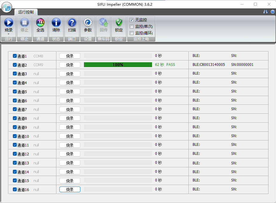
The Impeller main interface consists of a function button area, a channel display area, and a parameter configuration panel.
3.2 Channel Display Area
The channel display area shows port information, run status, and device serial number for all 16 channels. It also allows individual channels to be selected or started independently.
Channel Selection Click Select All to toggle all channels, or click an individual channel to toggle its selection.
Port Information Click Scan to scan and display the port for each channel. Channels with no connected device show “null”.
Run Control Click Run in the function area to start all selected channels simultaneously, or use each channel’s individual Run button. Once a channel is running its button changes to Stop; clicking it stops that channel.
Progress A progress bar and text field display the completion percentage and final result for each channel.
Run Time Displays the elapsed time for the current operation on each channel.
Device Info During flashing, shows the SN and BLE MAC of the device on each channel. During calibration, shows the result of each calibration item.
3.3 Flash Parameter Settings Panel
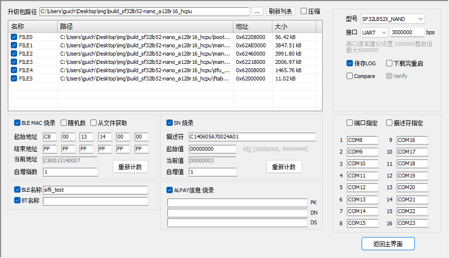
The flash parameter settings panel is shown above. Key controls are described below:
Package Path Paste the firmware package path into the edit box, or click the browse button to select it. If the package contains a
downfile.inifile, the firmware file list is populated automatically.File List After the package path is set, the list shows the recognized firmware files. The full path and address columns can be edited by double-clicking. Edits are temporary and will be reset when the list is refreshed.
Refresh List Refreshes the list, selects all files, and discards any manual edits.
Compress When checked, firmware packages for supported device types are compressed before flashing to improve speed. Supported device types are indicated in the
[UART_COMPRESS]section ofImpeller.ini. Checking this option has no effect on unsupported devices, so it is safe to leave it enabled. Disable it only if compressed flashing produces errors, for comparison purposes.BLE MAC Programming When checked, a BLE MAC address is written to each device. Three generation strategies are available:
Random The upper 2 bytes can be set to a fixed value; the lower 4 bytes are randomly generated.
Sequential Increment MACs are generated by incrementing from a starting value. When using sequential MACs across multiple PCs, manually partition the address ranges to avoid collisions.
From File MACs are read from an Excel file. Values must be in the first column of the first sheet, with three columns (MAC / Note / Used) and a header row.
From Network MACs are fetched from a server. This is a customer-specific customization.
SN Programming When checked, a serial number is written to each device (stored as ASCII). The SN consists of a descriptor (optional, user-defined string) and a numeric part (5–9 decimal digits). With a 5-digit starting value, the maximum is 99999; with a 9-digit starting value, the maximum is 999999999. The descriptor + number must not exceed 64 bytes. SN retrieval from a customer server is also available as a custom option.
BLE Name When checked, the BLE device name is written. Must not exceed 29 characters (subject to solution code constraints).
BT Name When checked, the Bluetooth classic device name is written. Must not exceed 29 characters (subject to solution code constraints).
ALPAY Info When checked, information required for AL Pay is written.
Device Type Selects the product type. The corresponding driver file is chosen based on this selection during flashing.
Interface Selects UART or JLink SWD. UART baud rate range: 1,000,000 – 6,000,000. JLink speed depends on the device; the default is typically 5000 kHz.
Download Control
Reboot After Download When checked, the device reboots after flashing, for convenient follow-up operations.
Compare When checked, a comparison is performed first; if the target address already contains the correct data, flashing is skipped. Typically disabled on production lines.
Verify When checked, a verification step is performed after flashing. Recommended to ensure correct programming.
Send Reset Command When using JLink, sends an
R(reset CPU) command before flashing.Send Hold Command When using JLink, sends an
H(halt CPU) command before flashing.JLink UI When using JLink, displays the downloader UI for easier monitoring. Not recommended for multi-channel downloads.
ERR BOX When using JLink, displays an error dialog box when an error occurs during flashing. Recommended to disable on production lines.
Device Filter Device filtering maps the tool’s channel display to the physically connected devices, making it easy to identify which device had a flashing error. If filtering is configured, each channel shows its designated device. Without filtering, discovered devices are assigned to channels in order (up to 16).
UART Channel Filter
Port Assignment Assigns a specific COM port to each channel for one-to-one mapping.
Descriptor Assignment If the UART adapter has an onboard EEPROM or similar chip that stores a descriptor, the descriptor can be edited to distinguish devices at the driver level. Assign a specific descriptor to each channel for one-to-one mapping.
JLink Channel Filter Assigns a specific JLink serial number to each channel for one-to-one mapping.
4 Operations
4.1 Production Line Setup
Before using on a production line, complete the configuration in the Flash Parameter Settings panel. Key items:
Select the device type (chip + storage type).
Select the flashing interface and speed. UART is typical for production lines; set the highest stable baud rate supported by the USB-to-serial adapter.
Check Save LOG. Uncheck Reboot After Download and Compare. Verify is checked by default.
Configure the device filter: connect devices one by one to the PC (channels 1–16) and assign each channel’s port number or descriptor.
4.2 Firmware Flashing
In the Run button drop-down menu, select the flash operation. The Run button and the settings panel button now display Flash.
Click Settings to open the parameter panel. Select the firmware package path and configure BLE MAC, SN, and other options as needed. Click Back to return to the main interface.
Each channel displays its connected device port. Click Flash to start all selected channels simultaneously, or use each channel’s individual Run button. During flashing, click Stop to halt all channels, or click a channel’s Stop button to halt only that channel.
After flashing completes, the per-channel status display shows whether each device succeeded.
4.3 Calibration
In the Run button drop-down menu, select the calibration operation. The Run button and the settings panel button now display Calibrate.
In the function area, check the calibration items to perform. Click the calibration parameter settings icon and configure the parameters (see Section 3.1 Calibration Items). Default parameters can generally be used without modification. Close the settings dialog when done.
Click Calibrate to start all selected channels simultaneously, or use each channel’s individual Run button. During calibration, click Stop to halt all channels, or click a channel’s Stop button to halt only that channel.
After calibration completes, the per-channel status display shows whether each device succeeded.
4.4 Flash Erase
In the Run button drop-down menu, select the erase operation. The Run button and the settings panel button now display Erase.
In the Erase FLASH area, check the erase items as needed (see Section 3.1 Erase FLASH).
Click Erase to start all selected channels simultaneously, or use each channel’s individual Run button. During erasing, click Stop to halt all channels, or click a channel’s Stop button to halt only that channel.
After erasing completes, the per-channel status display shows whether each device succeeded.
4.5 Combined Calibration + Flash
In the Run button drop-down menu, select Flash + Calibrate. The Run button and the settings panel button now display Flash+Cal.
Configuration is a combination of Sections 4.2 and 4.3.
This operation performs calibration first, then flashing. A combined result along with individual sub-item results is displayed after completion.