SiFli_EQ
1. Overview
SiFli_EQ is an in-house tool developed by SiFli Technology. Its primary function is to configure audio parameters on the target board — including volume levels, VBE, DRC, and EQ — for audio EQ tuning.
Tool path: tools/SiFli_EQ
2. Environment Setup
SiFli_EQ requires no installation and runs directly on Windows (XP / 7 / 10 / 11 …).
The EQ tool requires plugin registration on first use. Open it with administrator privileges the first time to avoid registration failure.
When using a serial port, the tool interacts with the board through the log system. The board firmware must have LOG_I level enabled and LOG_D level disabled; too many log messages at LOG_D level will interfere with correct communication.
3. Features
Audio processing pipeline: VBE (crossover filter → VBE → slope filter) → SOFT EQ → DRC (crossover filter → three-band DRC) → HARD EQ → Audio DAC
The tool has five tabs: Environment Settings, Volume Tuning, Hardware EQ Tuning, Software VBE/DRC, and Software EQ Tuning.
3.1 Common Controls
Save Data Saves the data from all tabs — including UI configuration and generated parameters.
Load All Data Restores saved data to all tabs.
Load Current Tab Data Restores only the saved data relevant to the current tab; other tabs remain unchanged.
Connection Indicator When the tool establishes a connection with the target board, the indicator turns green, indicating that live tuning is active — parameters can be read from or written to the board.
3.2 Environment Settings
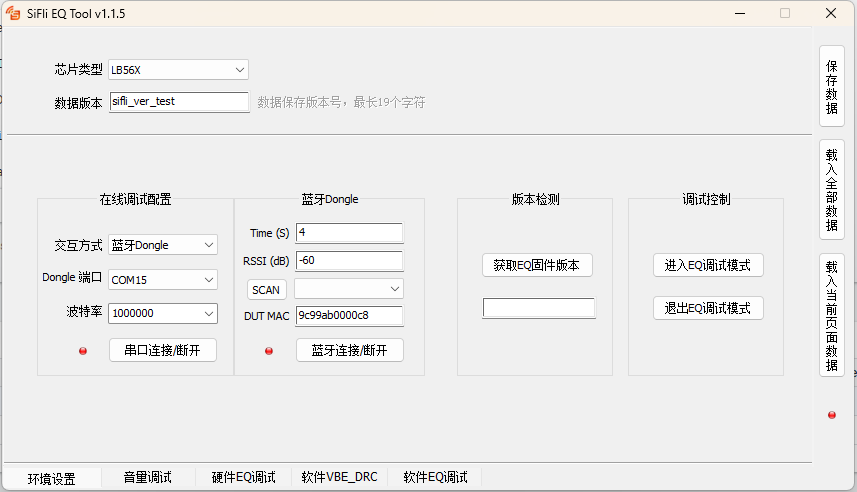
The Environment Settings tab is shown above. Key controls are described below:
Chip Type Some parameters may differ between chip types. This parameter is currently unused.
Data Version A version name for the generated data, up to 19 characters, for version tracking purposes.
Live Tuning Configuration
Interaction Method A communication channel must be selected before live tuning. Two methods are supported: DUT Serial Port and Bluetooth Dongle.
DUT Serial Port Sends commands directly through the target board’s HCPU Trace port. The board must have the Trace port exposed.
DUT Port Select the COM port corresponding to the target board’s HCPU Trace port.
Baud Rate Select the baud rate configured for the HCPU Trace port. Typically 1000000.
Connect / Disconnect Opens or closes the serial connection. The indicator turns green when connected, enabling live tuning.
Bluetooth Dongle Communicates via the Trace port of a Bluetooth Dongle. The BLE module exchanges data wirelessly with the target board, relaying information between the tool and the board. This is useful for boards that do not have a Trace port exposed. The Bluetooth Dongle is provided by SiFli Technology; contact your FAE to obtain one [TBD].
Dongle Port Select the COM port corresponding to the Bluetooth Dongle’s Trace port.
Baud Rate Select the baud rate configured for the Dongle’s Trace port. Typically 1000000.
Connect / Disconnect Opens or closes the serial connection. The indicator turns green when connected, enabling a BLE scan for the next step.
Time Sets the duration of the BLE scan for the target board.
RSSI Sets the RSSI threshold for filtering scan results. Devices below this threshold are not shown.
SCAN Scans for BLE devices and displays results in the list.
DUT MAC Specify the target board’s MAC address to connect directly, bypassing the scan step.
BLE Connect / Disconnect Connects or disconnects the Dongle from the target board over BLE. The indicator turns green on successful connection, enabling live tuning.
Version Check After the channel is established, click Get EQ Firmware Version. If the version cannot be retrieved, the tool cannot be used with this firmware. The retrieved version will be used for tool compatibility checking (currently not enforced).
Debug Control Live tuning requires entering EQ debug mode, which allows the tool to control the watch’s volume and other audio parameters. After exiting EQ debug mode, volume can be controlled from the phone again.
3.3 Volume Tuning
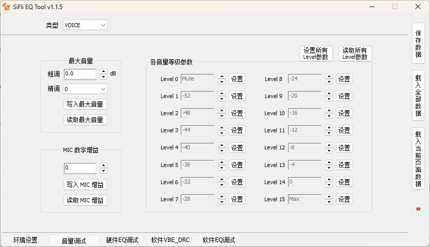
The Volume Tuning tab is shown above. Key controls are described below:
Type VOICE and MUSIC. Parameters for each type are tuned independently.
Max Volume
Coarse Adjust Increments or decrements in steps of 0.5 dB.
Fine Adjust Seven levels of fine adjustment; select 0 (no adjustment) in most cases. The coarse step is 0.5 dB; when higher precision is needed, set a fine adjust value — a higher value means more attenuation.
Write Max Volume Writes the volume value in the edit box to the target board.
Read Max Volume Reads the max volume value from the target board and displays it in the edit box.
MIC Digital Gain
Gain Value Range: 0 – 13 dB.
Write MIC Gain Writes the MIC gain value in the edit box to the target board.
Read MIC Gain Reads the MIC gain value from the target board and displays it in the edit box.
Volume Level Parameters
Write All Level Parameters Writes the gain values for all 16 levels to the target board.
Read All Level Parameters Reads the gain values for all 16 levels from the target board and displays them in the edit boxes.
Per-Level Settings Each level can be configured and written independently. Note: the last level’s value cannot exceed the max volume setting; the first level’s value cannot go below −54.
3.4 Hardware / Software EQ Tuning

The EQ Tuning tab is shown above. Hardware EQ and Software EQ operate in the same way. Hardware EQ supports up to 10 filter points; Software EQ supports up to 32.
Filter Parameter Settings Select a filter point on the right side, then set the filter type, frequency, gain, and Q value. In the graph area on the left, filter icons can be dragged to adjust the frequency and gain of the corresponding point. Ranges: frequency 10 Hz – 20 kHz; gain −12 dB – +12 dB; Q value 0.05 – 20.
Reset EQ Data Resets the parameters of all filter points to defaults.
Write EQ Writes the current EQ settings to the device’s memory.
3.5 Software VBE / DRC
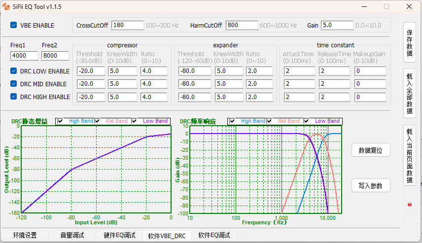
The Software VBE/DRC tab is shown above. The parameters are specialized filter-related values; each parameter shows its valid range as a comment.
VBE ENABLE Enables or disables the VBE feature.
Freq1 / Freq2 DRC crossover filter parameters.
DRC LOW / MID / HIGH ENABLE Enable switches for each DRC frequency band.
Reset Data Resets all parameters to default values.
Write Parameters Calculates the parameter results from the UI and writes them to the target board.
4. Board Configuration
In the board firmware (drv_audprc.c): to avoid re-writing EQ parameters after every reboot, the current debug parameters are written to EQ_DEBUG_FILE_PATH. This requires the filesystem to be configured. On the next boot, EQ parameters are loaded from that file. Modify these two macros to match your system — for example, if the /dyn/ directory does not exist, writing to EQ_DEBUG_FILE_PATH will fail. The directory must already exist before the file can be written.
#define EQ_DEBUG_FILE_PATH      "/dyn/eq_debug.bin"
#define EQ_SYSTEM_FILE_PATH     "/eq.bin"
EQ parameter priority (highest to lowest):
EQ_DEBUG_FILE_PATHEQ_SYSTEM_FILE_PATHParameters compiled into the firmware
EQ_DEBUG_FILE_PATH is for temporary use during tuning and must not be present in release builds. EQ_SYSTEM_FILE_PATH is the production file that is flashed or OTA-updated on the device; the exact path is product-dependent (the root directory shown here is just an example).
/dyn/eq_debug.bin is generated when EQ debug mode is exited.
/eq.bin is generated when Save Data is clicked in the EQ tool, and is then flashed to or OTA-updated on the device.
The generated code must be integrated into drv_audprc.c:
int8_t g_tel_vol_level[16]— gain values (in 1 dB units) for 16 volume levels during calls.int8_t g_music_vol_level[16]— gain values (in 1 dB units) for 16 volume levels during media playback.g_tel_max_vol— maximum gain during calls, in 0.5 dB units. All values ing_tel_vol_level[]must be ≤g_tel_max_vol × 2.g_music_max_vol— maximum gain during media playback, in 0.5 dB units. All values ing_music_vol_level[]must be ≤g_music_max_vol × 2.
To make a simple volume adjustment, the array values can be edited manually. Note that the gain returned for a given volume level (in 0.5 dB units) is compared against the maximum gain — if it exceeds the maximum, the maximum is returned instead.
5. Usage
The tool is straightforward to use. However, making meaningful adjustments requires familiarity with audio processing and filter theory, which is beyond the scope of this document.