
Debugging Tools Environment Configuration Guide
This section describes how to download and configure the debugging tools.
1 Trace32
1.1 Trace32 Download and Configuration
1.1.1 Download Trace32
You can download it directly from the Lauterbach official website, as shown below. Select the ARM version simarm.zip. The free version has limitations on online debugging and script length. SiFli’s full MCU series currently only uses the offline debugging functionality.
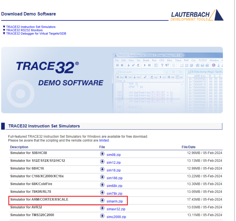
Lauterbach offline debugging tool download link: Simulator for ARM/CORTEX/XSCALE simarm.zip
1.1.2 Configuration
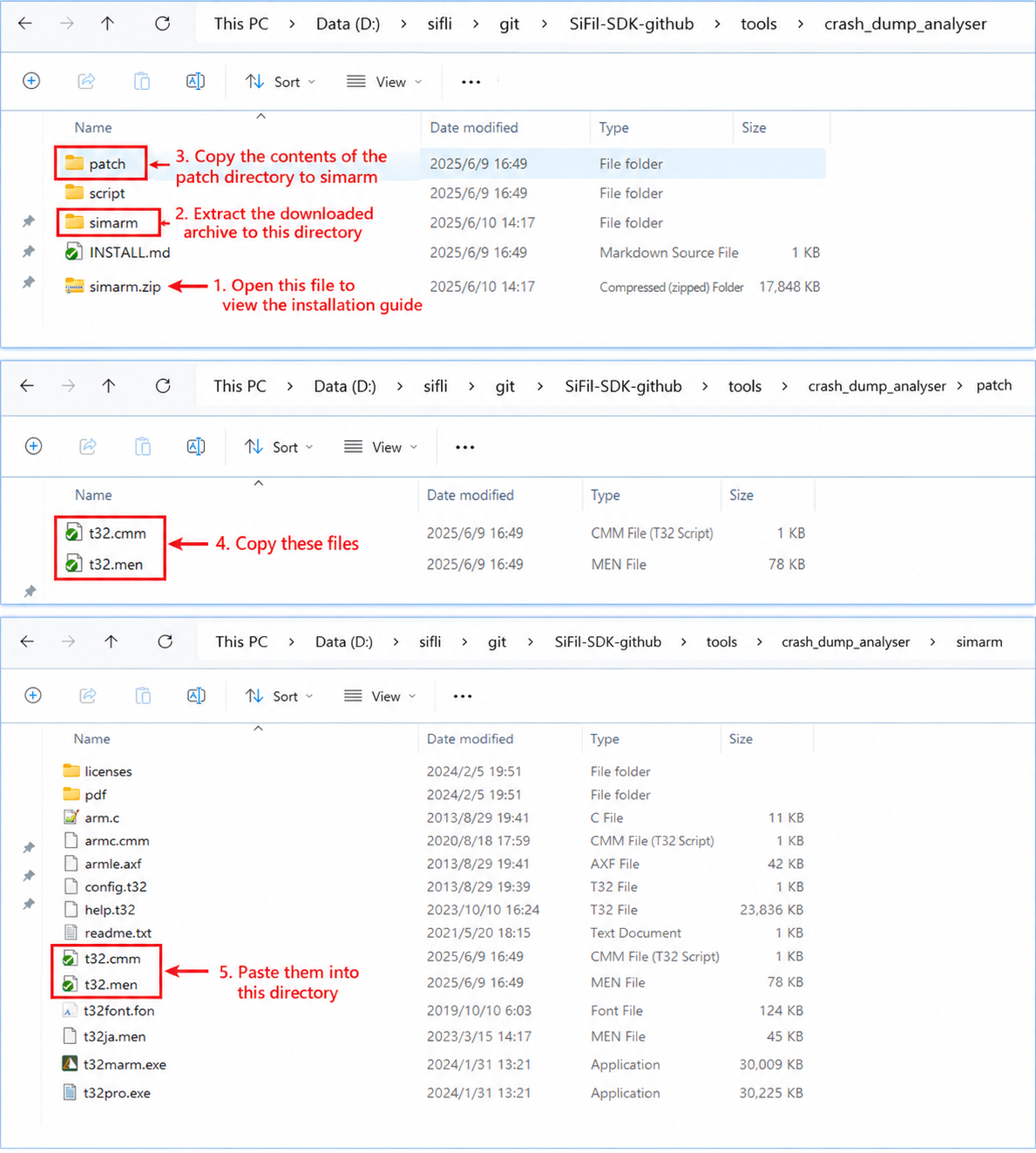
Extract the downloaded archive to the SiFli-SDK\tools\crash_dump_analyser\ directory, then copy the contents of the patch folder in this directory into the extracted simarm directory, as shown below:
1.1.3 Running Trace32
This software requires no installation. Double-click the t32marm.exe executable in the simarm directory to open Trace32.
2 Ozone
2.1 Ozone Download and Configuration
2.1.1 Download Ozone
You can download it directly from the SEGGER official website. For Windows systems, select the Windows version.
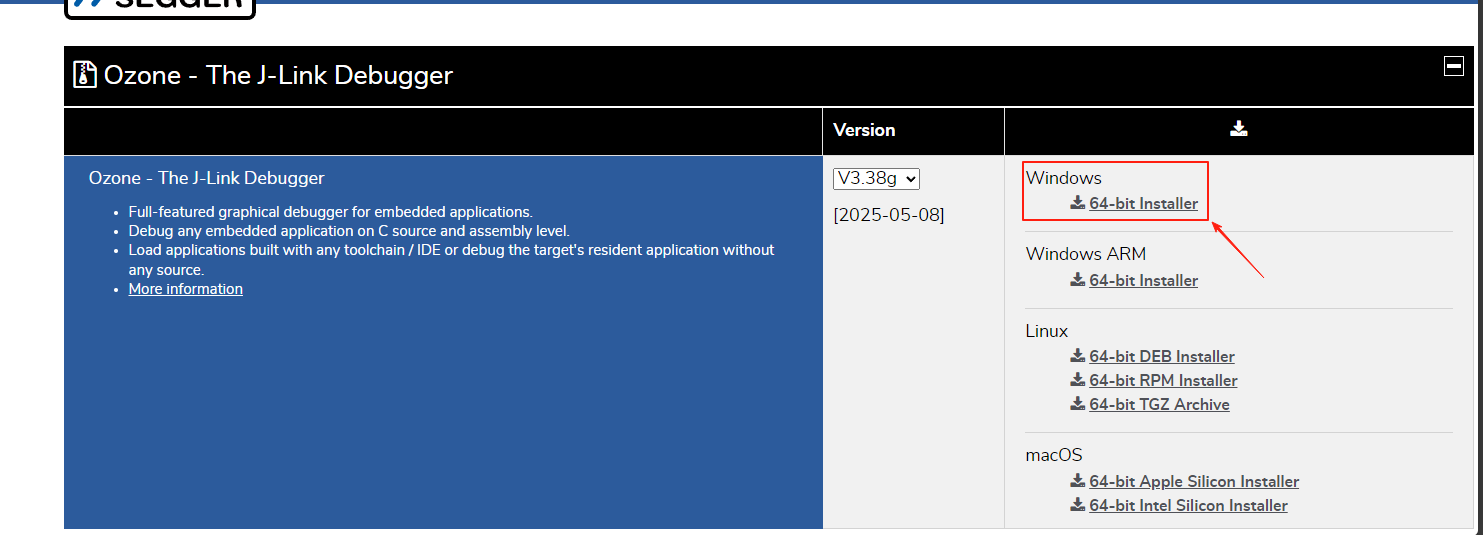
SEGGER online debugging tool download link: Ozone - The J-Link Debugger Windows 64-bit Installer
Note: Ozone and J-Link versions above V7.6 will check for counterfeit J-Link debuggers. For learning purposes, you can use Ozone_Windows_V320d_x64.exe and JLink_Windows_V758a_x86_64.exe.
2.1.2 Configure Device, MCU Peripheral Registers, and RT-Thread OS Script
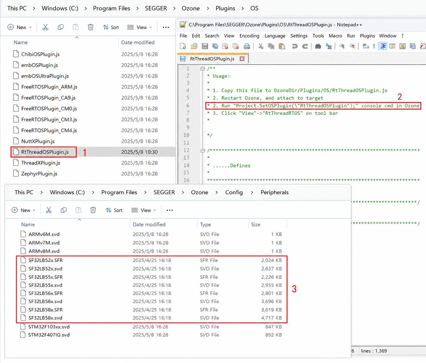
A. Replace the Ozone configuration file C:\Users\yourname\AppData\Roaming\SEGGER\JLinkDevices\JLinkDevices.xml with SiFli-SDK\tools\flash\jlink_drv\JLinkDevices.xml. Additionally, create a SiFli directory under C:\Users\yourname\AppData\Roaming\SEGGER\JLinkDevices\Devices\, and copy all contents from the subdirectories of SiFli-SDK-i\tools\flash\jlink_drv into the created SiFli folder. The corresponding directories and files are as follows:
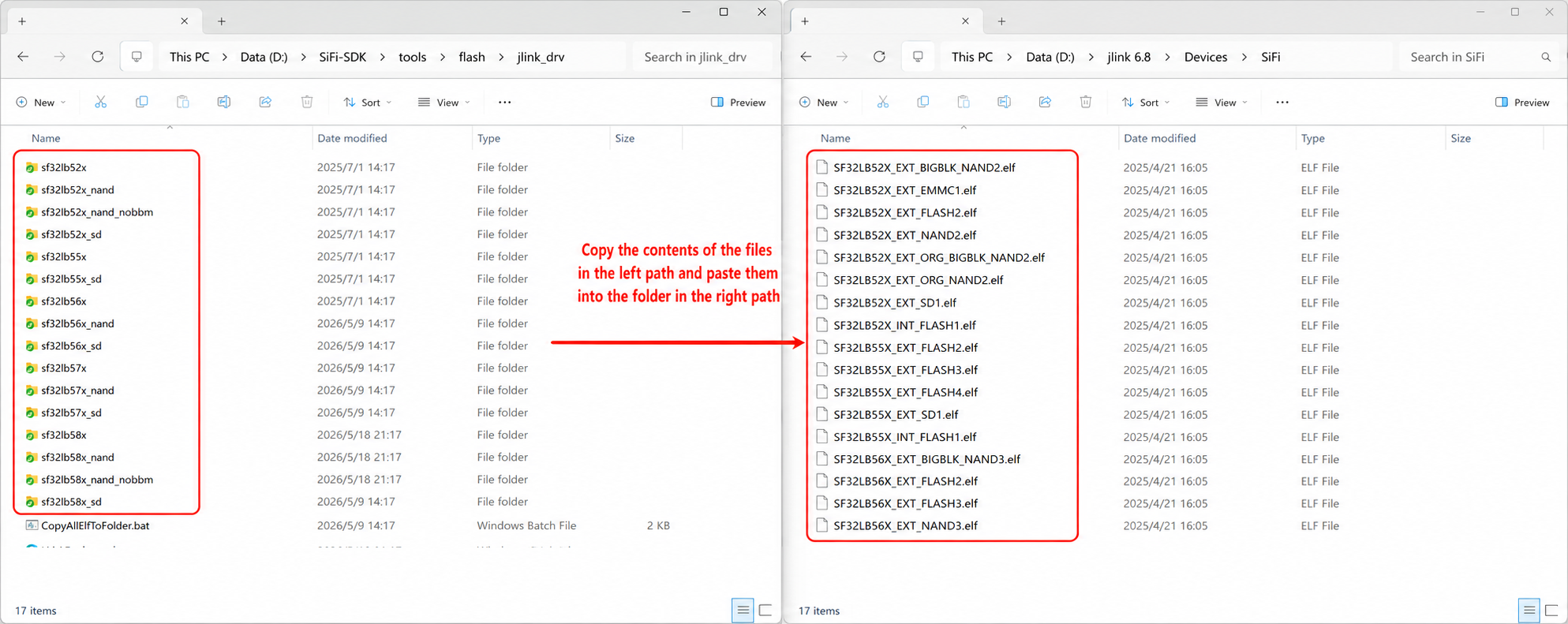
The J-Link flash driver correspondence can be found in the JLinkDevices.xml file:
<Device>
    <ChipInfo Vendor="SiFli" Name="SF32LB52X_NOR" Core="JLINK_CORE_CORTEX_M33" WorkRAMAddr="0x20000000" WorkRAMSize="0x60000" />
    <FlashBankInfo Name="Internal Flash1" BaseAddr="0x10000000" MaxSize="0x8000000"  Loader="Devices/SiFli/SF32LB52X_INT_FLASH1.elf" LoaderType="FLASH_ALGO_TYPE_OPEN" AlwaysPresent="1"/>
    <FlashBankInfo Name="External Flash2" BaseAddr="0x12000000" MaxSize="0x8000000" Loader="Devices/SiFli/SF32LB52X_EXT_FLASH2.elf" LoaderType="FLASH_ALGO_TYPE_OPEN" AlwaysPresent="1"/>
</Device>
B. Copy all contents from the subdirectories of SiFli-SDK\tools\svd_external to C:\Program Files\SEGGER\Ozone\Config\Peripherals.
C. Copy SiFli-SDK\tools\segger\RtThreadOSPlugin.js to C:\Program Files\SEGGER\Ozone\Plugins\OS\. The corresponding directories and files are as follows:
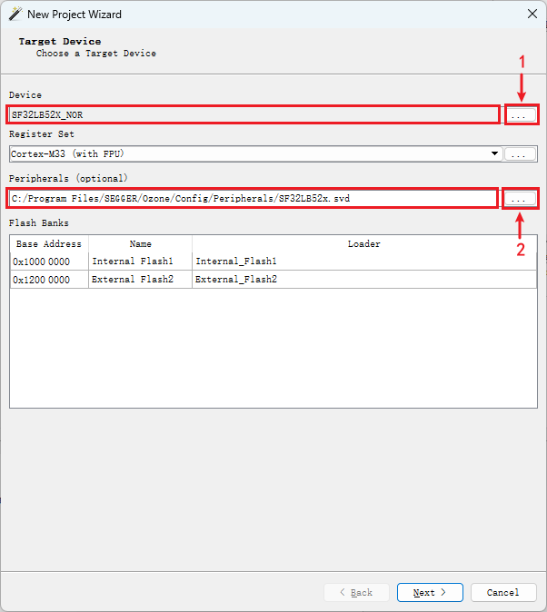
After configuring items A/B/C, open Ozone and you will be able to select the desired Devices and MCU peripheral registers:
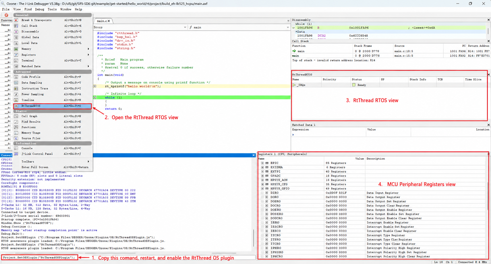
After configuring the MCU peripheral registers and RT-Thread OS script, enter the Ozone interface to view the corresponding MCU peripheral registers and OS threads:
3 J-Link
J-Link can be downloaded from the official website. Please use JLink V7.62 or later. After installation, create a SiFli folder under the jlink\Devices\ directory:
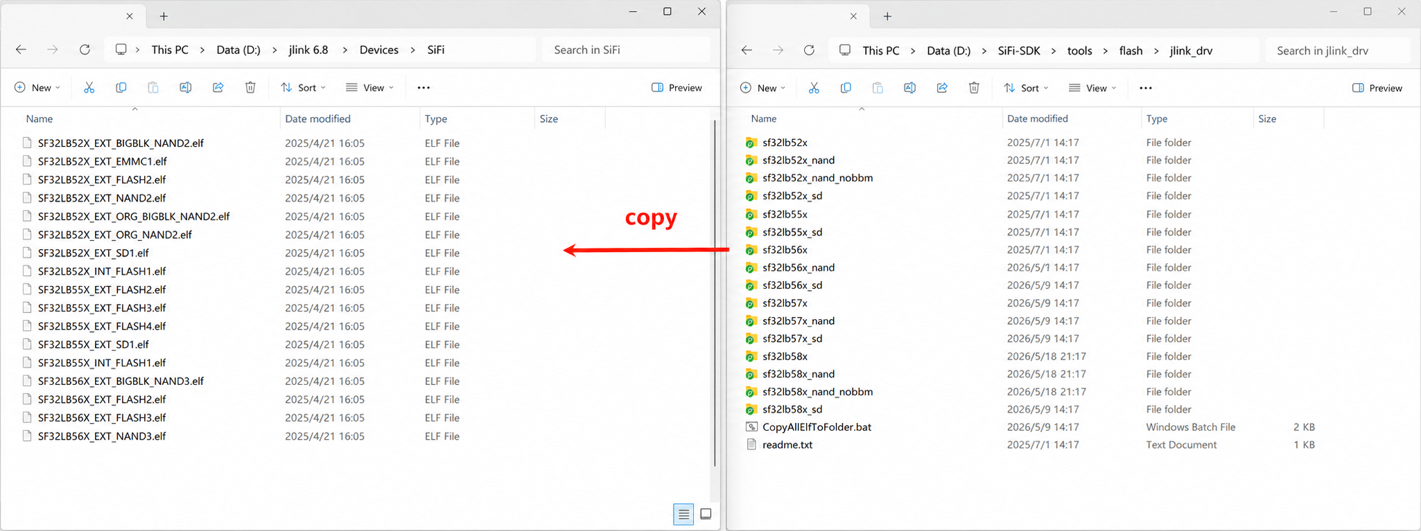
D:\jlink 6.8\Devices\SiFli
Copy the entire contents of tools/flash/jlink_drv from the SDK into this directory. After copying, the directory should contain at least JLinkDevices.xml and subdirectories such as sf32lb55x.
Notes:
tools/flash/jlink_drvis the complete J-Link Device Support Kit (DSK) package. TheJLinkDevices.xmlin the root directory describes devices and flash banks, and the elf files in subdirectories are the corresponding Open Flashloader algorithms.Starting from J-Link V7.62, it recursively scans all
*.xmlfiles under theJLinkDevicesdirectory. Therefore, there is no need to modify theJLinkDevices.xmlin the J-Link installation directory, nor to manually flatten-copy elf files to theDevices\SiFlidirectory.Loader paths in the XML are resolved relative to
JLinkDevices.xml, so the entiretools/flash/jlink_drvdirectory contents must be copied together.
3.1 J-Link Connection
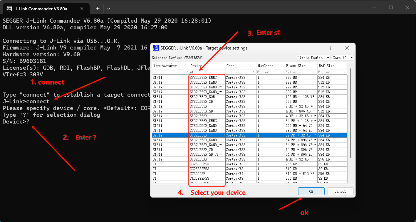
Open the SiFliUsartServer tool, located at SiFli-SDK\tools\SifliTrace\UsartServer. Then open J-Link Commander and follow the steps shown below to connect the device:

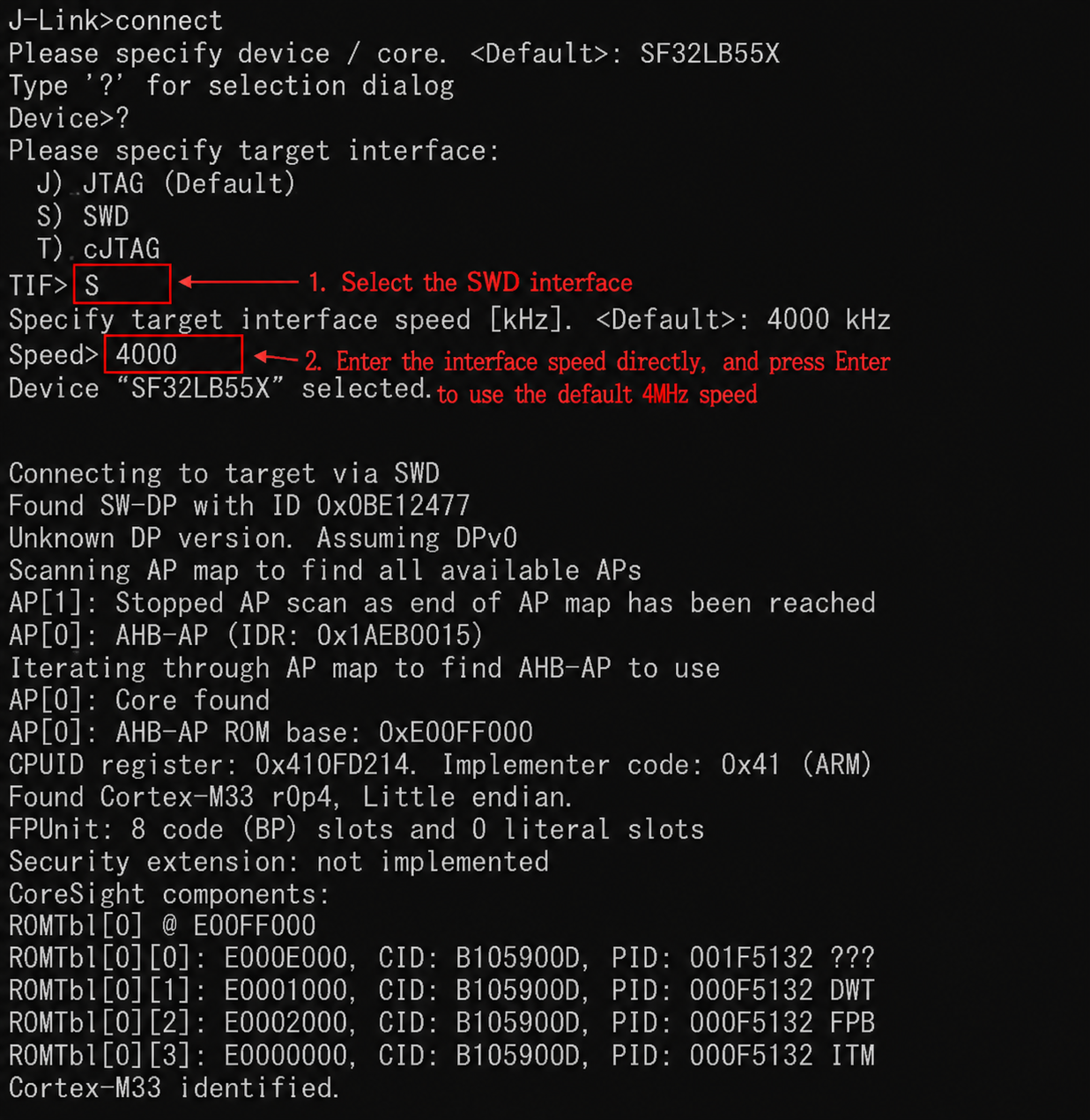
Select the SWD interface and configure the speed:
3.2 J-Link Usage Issues
HCPU Log Cannot Be Printed via Jlink Segger
Root cause: In newer SDK versions, to optimize memory usage, the J-Link Control block address variable _SEGGER_RTT was moved from HPSYS SRAM 0x20000000 to memory region HPSYS ITCM RAM 0x00010000 - 0x0001FFFF (64 * 1024), as shown below:
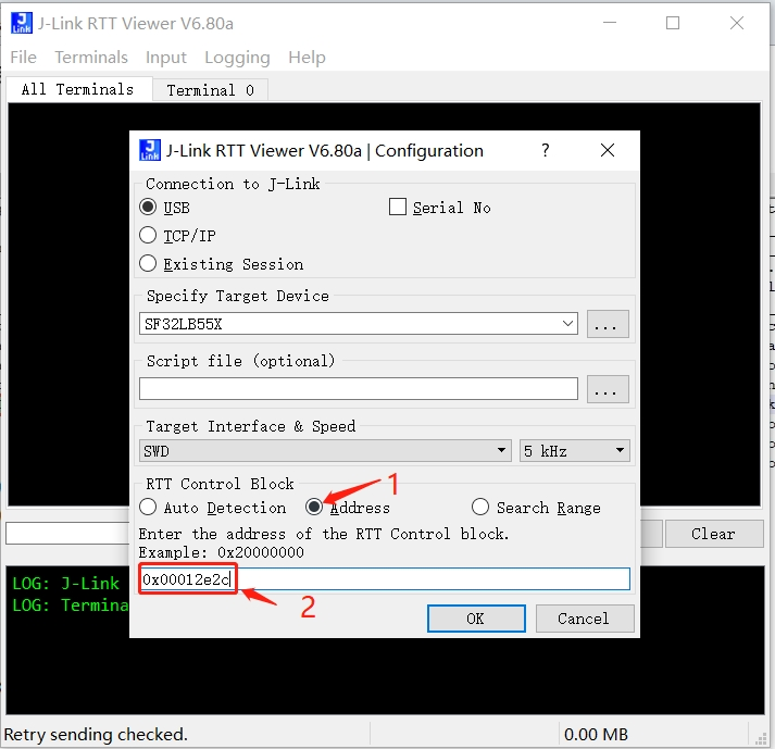
J-Link searches memory starting from 0x20000000 by default, so it cannot find the variable and connection fails. Older SDK version 0.9.7 compiled the address after 0x20000000, which J-Link could automatically find.
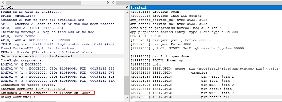
Solution 1: Specify the address in J-Link RTT Viewer.exe. This address can be found by searching the map file, as shown below:
Solution 2: Use Ozone.exe instead. Ozone.exe can find this address through the axf file. As shown below, there is a SetRTTAddr command:
Solution 3: Create a JLinkScript command that will automatically be called when J-Link starts, to set up or search the Control block address range. See the commands below (you can modify as needed):
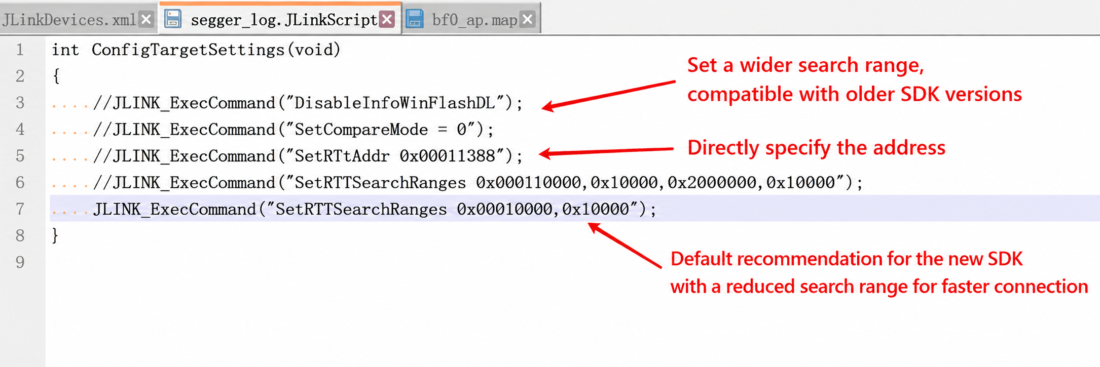
Corresponding XML file modification:
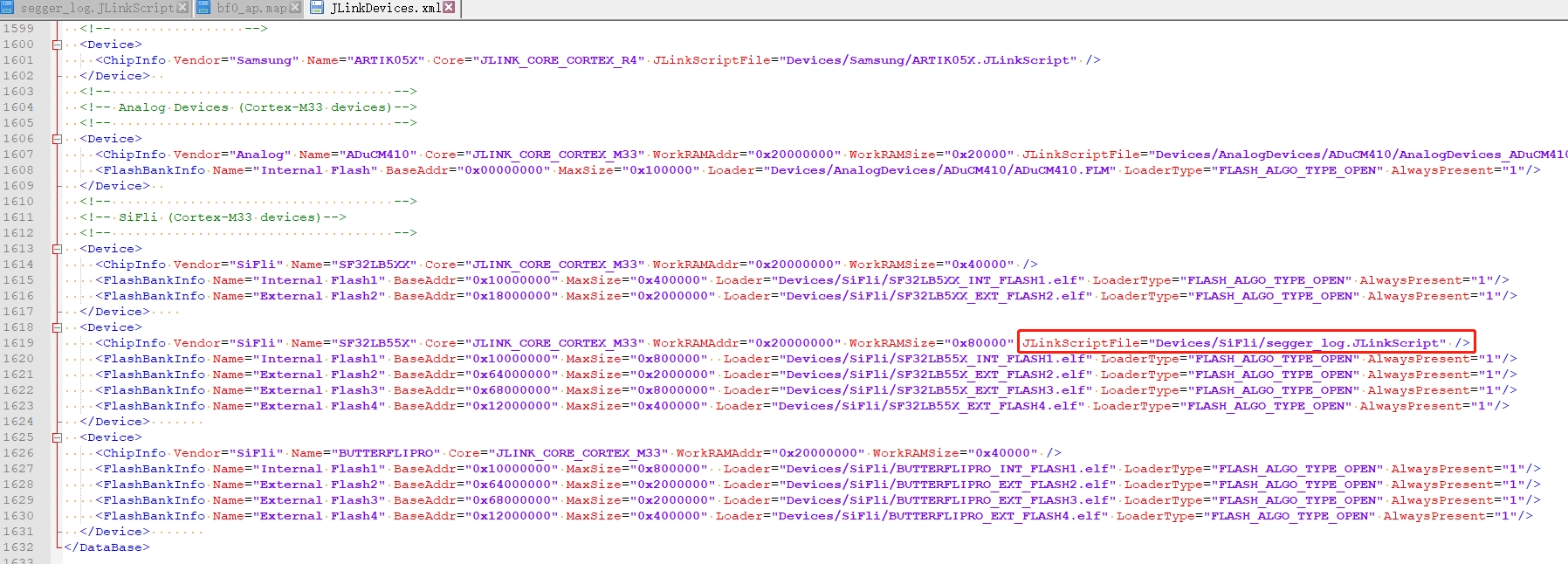
JLink.exe and J-Link RTT Viewer.exe will then automatically connect as before, which is much more convenient. It is recommended to use rttview.exe and telnet 127.0.0.1 to view logs. The patch file is attached; copy it to the corresponding J-Link installation directory:
Program Files (x86).7z
How to Read/Write Flash Content with Jlink
After J-Link connection is successful, use
mem32to read,w4to write, anderaseto erase:
mem32 0x40014000 1 #Read one 32-bit register value
mem32 0x64000000 10 #Read 10 bytes starting from flash2 address 0x64000000
w4 0x64000000 0x2f 0x2f 0x2f 0x2f 0x2f 0x2f #Write memory or register values, starting from flash2 address 0x64000000, writing the subsequent data
Use J-Flash to read/write: In the same directory as jlink.exe, there is a jflash tool. Use the menu shown below to read flash content:
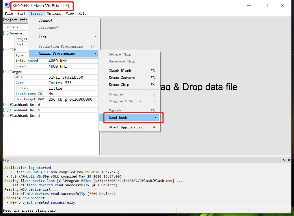
savebincommand for reading:
savebin d:\1.bin 0x101b4000 0x100000
Above, 0x101b4000 is the memory address and 0x100000 is the read/write memory size (in bytes). To write the saved bin file back:
loadbin d:\1.bin 0x101b4000
Other Common Jlink Commands
haltandgocommands: Typehto halt the CPU and check the current PC pointer position; typegto resume CPU execution.
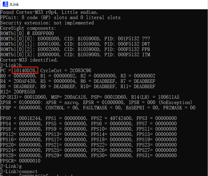
Set PC pointer: Commonly used with the
__asm("B .");instruction. When code execution reaches this instruction, it will halt. As shown above, if the PC pointer is at0x10140D28, add 2 to the PC pointer by typingsetpc 0x10140D2Ato skip the__asm("B .");instruction and continue execution.Other commands:
erase 0x00000000.0x0000FFFF
loadbin <filename> <address> -- Download filename to address
usb -- Connect to the target board
r -- Reset the target board
halt -- Stop the running program on CPU
loadbin -- Load executable binary file
g -- Jump to code segment address and execute
s -- Single step execution (for debugging)
setpc -- Set the PC register value (for debugging)
setbp -- Set breakpoint, after breakpoint halt, use g to continue execution
Regs -- Read register set
wreg -- Write register
mem -- Read memory
w4 -- Write memory