
SiFli SF32LB5xx Bluetooth Signaling Test Guide
1. Introduction
In signaling test mode, once the device under test (DUT) has connected to the comprehensive tester, you can run automated tests by controlling the tester with a software tool (for example, using R&S®CMWrun to control a CMW tester), or measure the DUT’s metrics by operating the tester manually. This document focuses on how the DUT establishes a signaling connection with the tester and performs TX and RX testing, to help hardware engineers carry out Bluetooth signaling testing on the SF32LB55x/58x/56x/52x/57x series chips, using the CMW500 tester as an example.
The following resources are required for the test:
Hardware
A comprehensive tester
A device under test (DUT, referred to as EUT in some documents)
A Windows PC
A USB-to-serial cable
An RF coaxial cable
Software
A serial tool (e.g. the SiFli_Trace tool)
BLE has no officially defined test mode, so a serial connection to the tester is required. A typical BLE signaling test topology is shown in Figure 1-1.
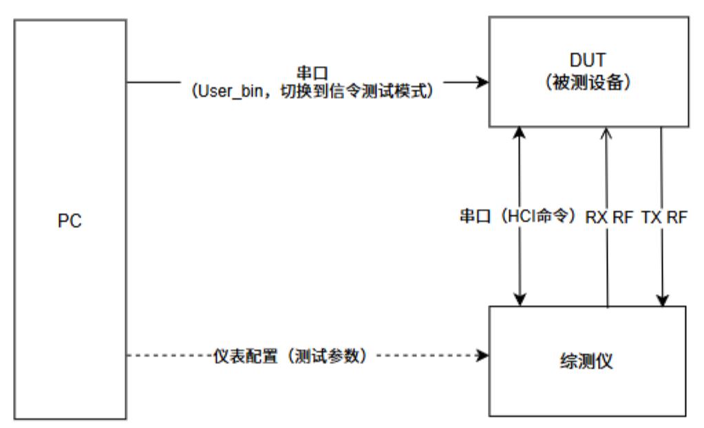
Figure 1-1
The difference between BT signaling testing and BLE signaling testing is that BT signaling testing does not require a serial connection to the tester. A typical BT signaling test topology is shown in Figure 1-2.
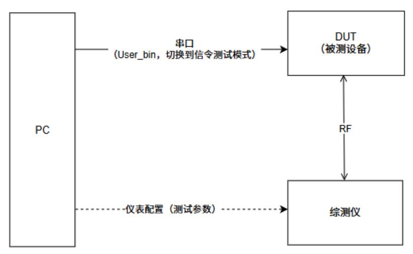
Figure 1-2
2. Test Preparation
2.1. Hardware Wiring
1. DUT test-point leads
Lead out the following test points for power supply and serial communication: VBAT, GND, UART1 TX/RX.
2. Chip serial pin mapping
The UART1 pins differ between models; the mapping is shown in Table 1:
Table 1
Pin name |
SF32LB551 |
SF32LB555 & 557 |
SF32LB56xU |
SF32LB56xV |
SF32LB58x |
SF32LB52x / SF32LB57x |
|---|---|---|---|---|---|---|
UART1 TX |
PA17 |
PA34 |
PA17 |
PA34 |
PA32 |
PA19 |
UART1 RX |
PA18 |
PA30 |
PA18 |
PA30 |
PA31 |
PA18 |
Note: SF32LB52x denotes all 52-series parts, SF32LB57x denotes all 57-series parts, SF32LB58x denotes all 58-series parts, SF32LB56xU is the QFN package (e.g. SF32LB563), and SF32LB56xV is the BGA package (e.g. SF32LB567). The pins above are the default pin configuration; in practice, use the specific pins configured for your project.
Environment setup: Connect the DUT’s UART1 to the PC, used to send the command to enter test mode; connect the RF to the tester via a coaxial cable to test RF performance. (For BLE signaling testing, the serial port must be connected to the tester after entering test mode.)
2.2. DUT entering BLE test mode
Power on the DUT and make sure it boots normally;
Make sure the DUT is not in sleep mode, and connect the DUT’s UART1 to the PC with a USB cable;
Use a serial tool (e.g. the SiFli_Trace tool) to send the Finsh command
bt_cm uart_dutto the DUT;Switch the serial tool to “HEX” display; receiving the reply
04 0E 04 XX 03 0C 00indicates the DUT has successfully entered test mode, as shown in Figure 2-1;In the serial tool, disconnect the serial connection;
Move the USB cable from the PC to the tester (i.e. connect the DUT’s UART1 to the tester via the USB cable).
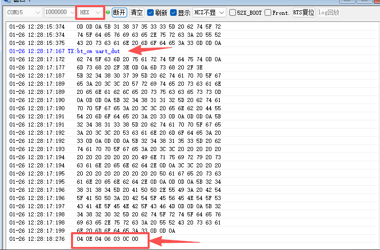
Figure 2-1
2.3. DUT entering BT test mode
Power on the DUT and make sure it boots normally. If the DUT has already entered BLE test mode, power-cycle it to reboot.
With the screen on (do not let the DUT go to sleep), connect the DUT’s UART1 to the PC with a USB cable;
Use a serial tool (e.g. the SiFli_Trace tool) to send the Finsh command
bt_cm dutto the DUT;With the serial tool in “character” (ASCII) display, receiving the reply
Write scan enable successindicates the DUT has successfully entered test mode. Because User_bin produces other logs as well, the actual reply looks like Figure 2-2;
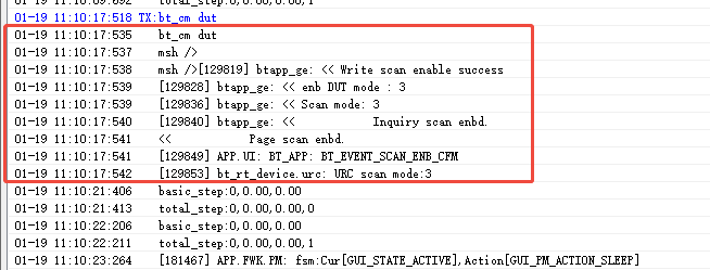
Figure 2-2
3. Establishing a Signaling Connection
3.1. Basic instrument setup
On the tester’s key panel, find SIGNAL GEN at the top left and press it (Figure 3-1) to open the instrument selection screen;
Select Bluetooth signaling (Figure 3-2) to open the Bluetooth signaling setup screen;
On the signaling setup screen, Bluetooth signaling is OFF by default (Figure 3-3);
Now click Bluetooth signaling and then press ON/OFF on the key panel to turn the test on (Figure 3-4); the basic instrument setup is complete.
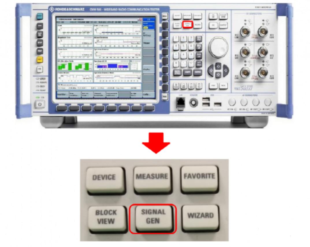
Figure 3-1
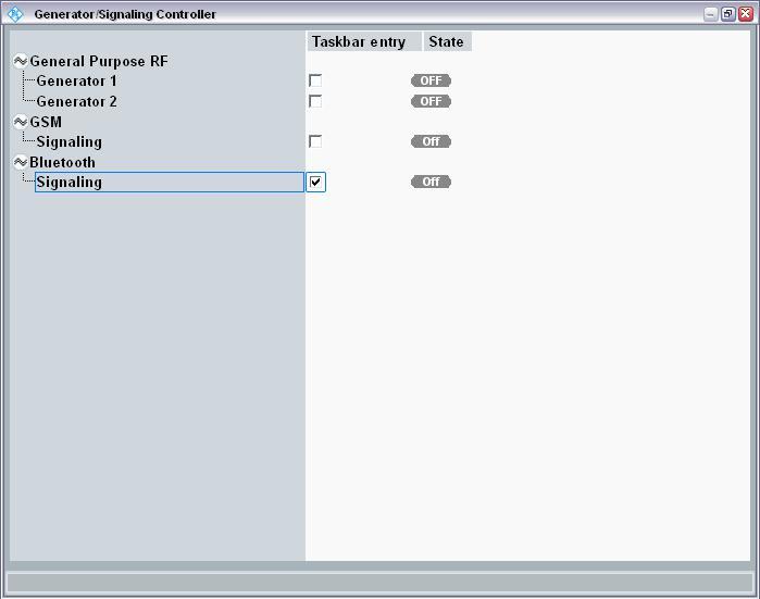
Figure 3-2
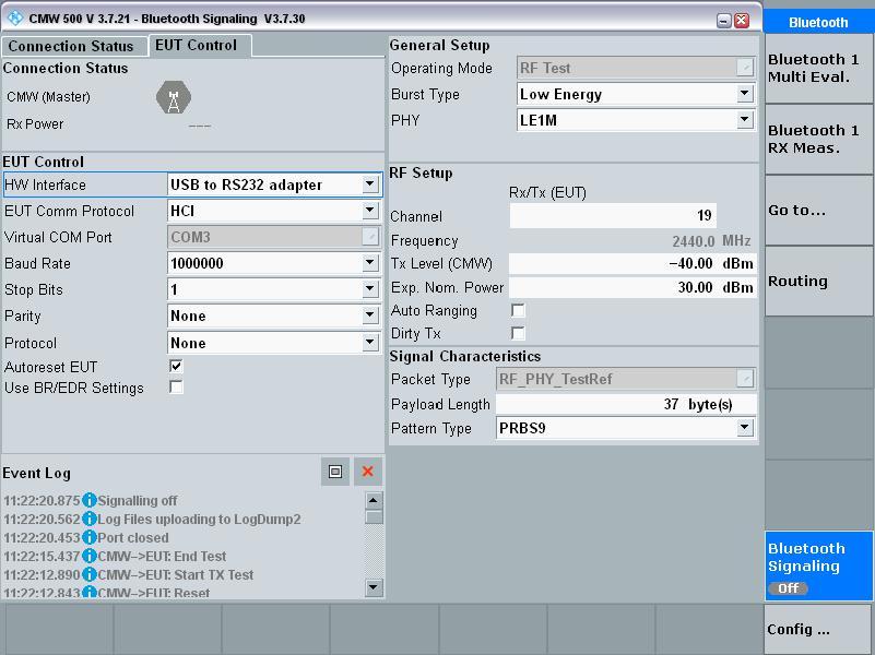
Figure 3-3
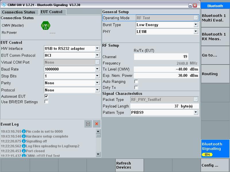
Figure 3-4
3.2. Establishing a BLE signaling connection
The BLE signaling test topology is shown in Figure 1-1; interaction with the tester is over serial.
On the Bluetooth signaling screen, click EUT Control; in the screen that appears, configure as in Figure 3-5: set HW Interface to
USB to RS232 adapter, Baud Rate to1000000, and Burst Type toLow Energy. At this point, with no serial port plugged in, the Virtual COM port field is grayed out;
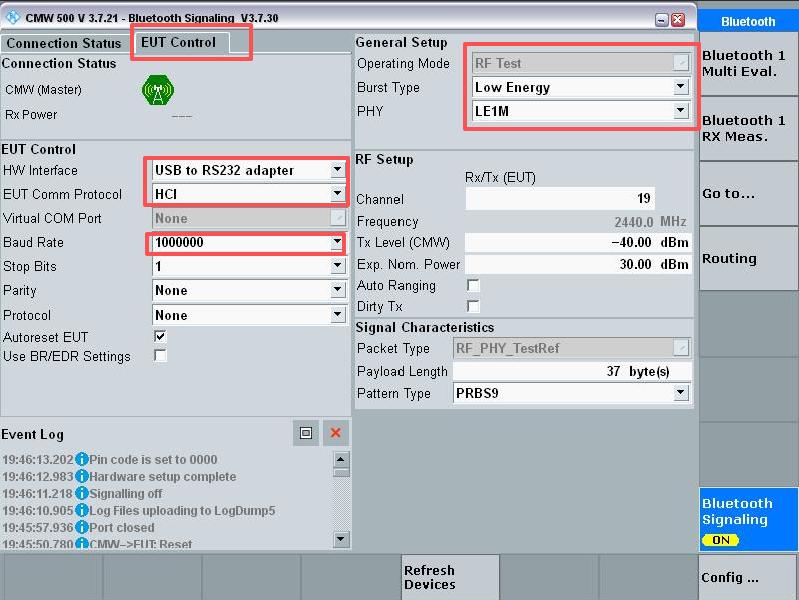
Figure 3-5
Connect the DUT’s UART1 (for the UART1 of each chip model, refer to Table 1) to the tester (with the DUT already in test mode; for the User_bin entry method, see Chapter 2), and connect the DUT’s RF coaxial cable to the tester’s RF input. Now toggle Bluetooth signaling off and on again, and the instrument automatically detects the serial port, as shown in Figure 3-6;
After the instrument recognizes the serial port, click connection check at the bottom left; after about 3 s a pop-up appears showing
LE comm test passed. Click OK, and you can then run automated or manual tests; if the instrument is connected to automation software, you can run automated tests.
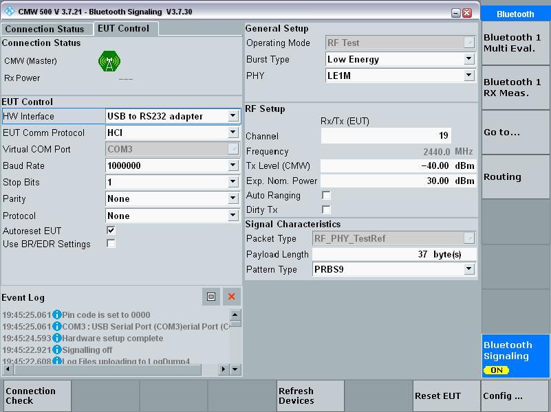
Figure 3-6
3.3. Establishing a BT signaling connection
The BT signaling test topology is shown in Figure 1-2; a BT signaling connection to the tester does not require a serial port.
The Bluetooth signaling screen setup differs from the BLE connection, as shown in Figure 3-7: the main change is setting the HW Interface option to
None (EUT Control off);Confirm that the DUT has entered signaling test mode (for the User_bin entry method, see Chapter 2) and that the RF coaxial cable is connected to the tester. Click Inquire at the bottom left to scan for Bluetooth; once the DUT’s Bluetooth address is found, stop the scan and click Connect Test Mode to connect to the DUT. A successful connection is shown in Figure 3-8.
After connecting successfully, you can run automated or manual tests; if the instrument is connected to automation test software, you can start the automation.
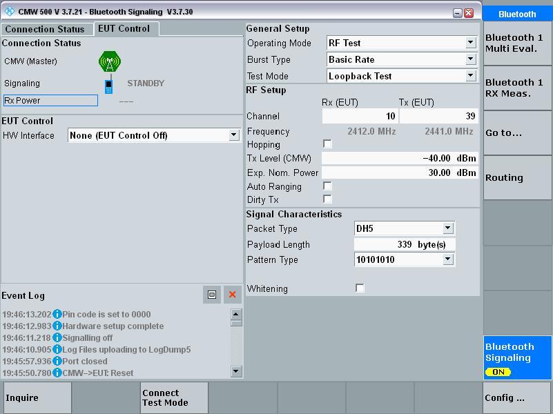
Figure 3-7
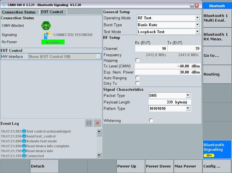
Figure 3-8
4. TX Test (common to BLE/BT)
After a BLE or BT signaling connection is established, the manual TX test procedure is the same for both.
After the DUT and the tester are connected, on the Bluetooth signaling screen click Bluetooth 1 Multi Eval. (Figure 4-1);
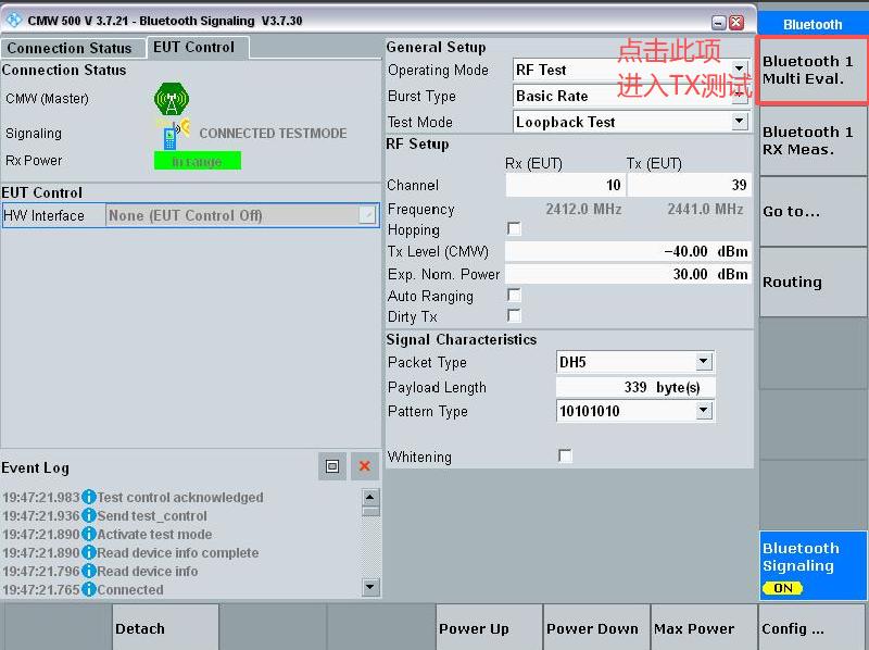
Figure 4-1
The TX screen it jumps to is off by default (Figure 4-2);
Press ON/OFF to turn the test screen on; once the Multi Evaluation test is on, the screen shows the DUT’s test results, as in Figure 4-3.
To test other parameters — for example, switching a BLE test to BLE 2M or a BT test to EDR — select Input Signal on the right side of the screen, then choose the corresponding option under Burst Type at the bottom of the instrument screen. To change the packet type, packet length, etc., set them on the Bluetooth signaling screen, or click the Input Signal button and choose the corresponding options at the bottom of the screen, as shown in Figure 4-4.
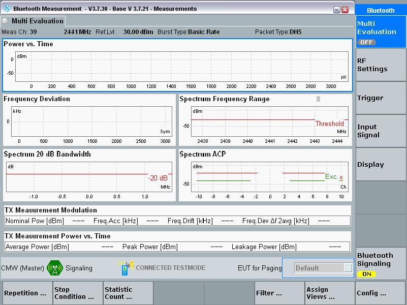
Figure 4-2
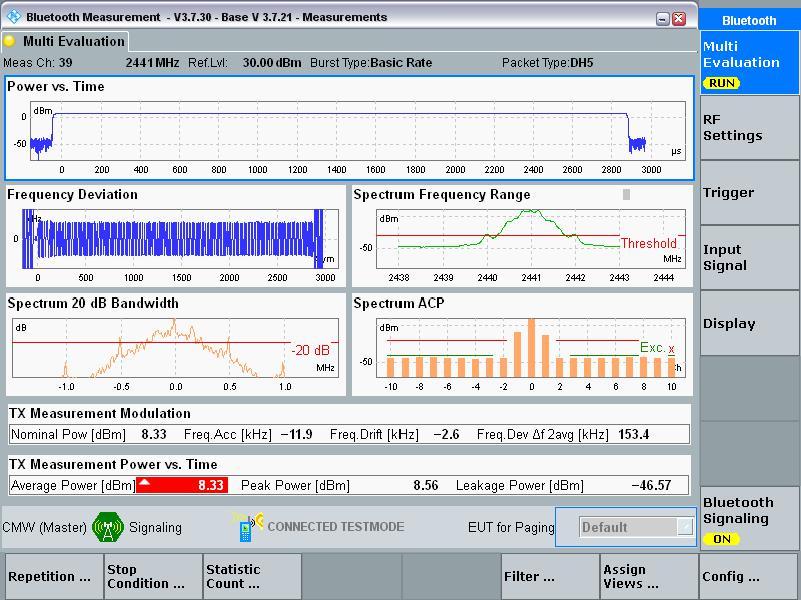
Figure 4-3
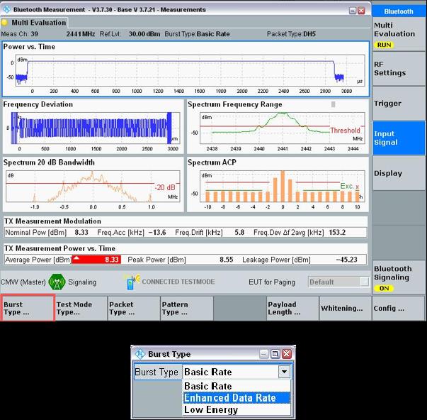
Figure 4-4
5. RX Test (common to BLE/BT)
After a BLE or BT signaling connection is established, the manual RX test procedure is the same for both. If you proceed to the RX test after finishing the TX test, first select Bluetooth 1 Multi Eval., press ON/OFF to turn off the TX test, and click Bluetooth signaling on the right side of the screen to return to the connection screen.
On the Bluetooth signaling screen, click Bluetooth 1 RX Meas. (Figure 5-1);
The RX screen it jumps to is off by default (Figure 5-2);
Select BER/PER at the top left (BER for BT tests, PER for BLE tests), set the channel, packet type, packet length, etc. to be tested, then press ON/OFF to turn on Rx Quality. The BT RX test configuration screen is shown in Figure 5-3 and the BLE RX test configuration screen in Figure 5-4;
Select Tx Level (CMW) on the screen and slowly decrease the Tx Level value (you can decrease it in steps of 0.01 or 0.1). When the PER[%] or BER[%] value at the top left of the screen turns red, the previous value is the receiver sensitivity of the channel under test, as shown in Figure 5-5;
To test the receiver sensitivity at other frequencies or of other types, simply change the corresponding settings.
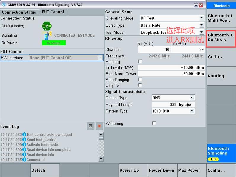
Figure 5-1
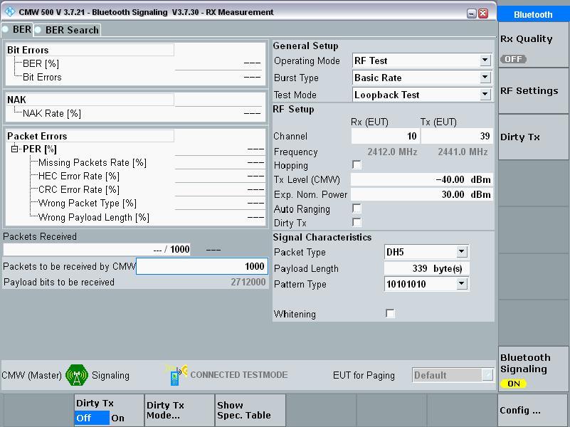
Figure 5-2
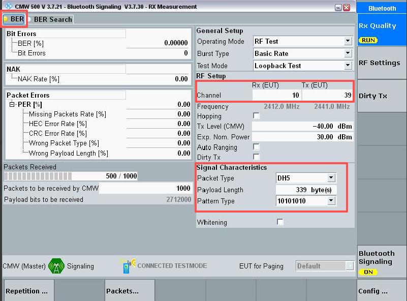
Figure 5-3
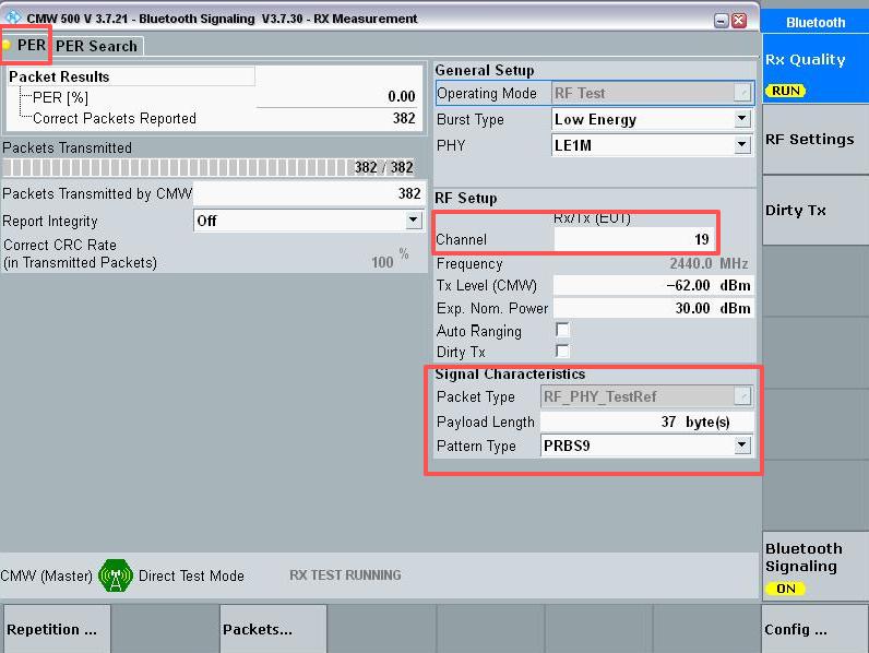
Figure 5-4
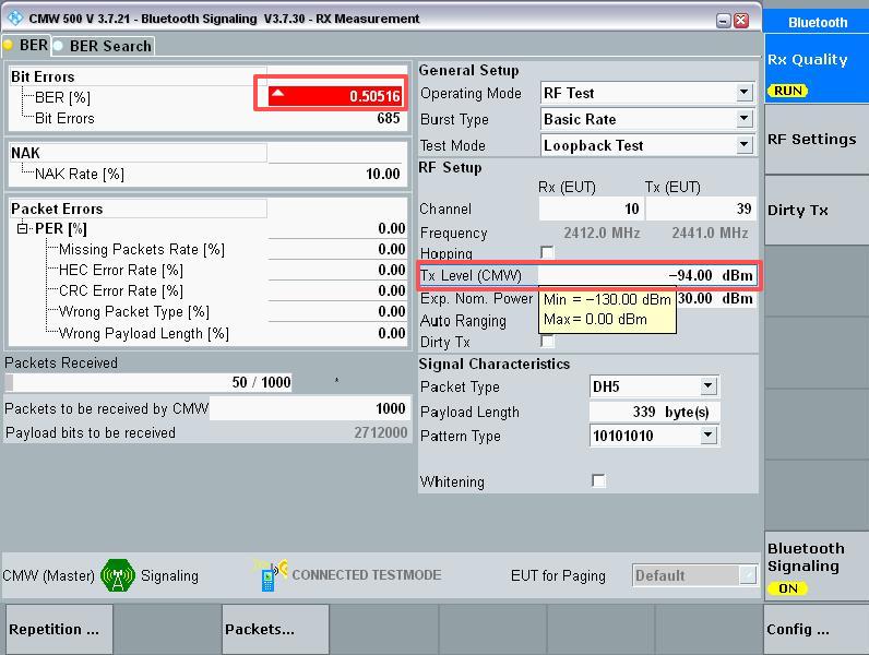
Figure 5-5