
SiFli SF32LB5xx Bluetooth Individual RF Test Guide
1. Introduction
The main purpose of this document is to help engineers carry out individual Bluetooth RF tests on SF32LB5xx chips. The following resources are required for the test:
Hardware
A comprehensive tester / spectrum analyzer
A device under test (DUT, referred to as EUT in some documents)
A Windows PC
A USB Type-C data cable (Note: it must not be a charge-only Type-C cable)
An RF coaxial cable
Software
The SiFli_RfTool tool
The test topology is shown in Figure 1-1: the DUT connects to the PC over serial, and the RF connects to the comprehensive tester via a coaxial cable.
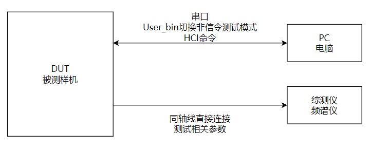
Figure 1-1
2. Test Preparation
2.1. Hardware Wiring
1. DUT test-point leads
Lead out the following test points for power supply and serial communication: VBAT, GND, UART1 TX/RX.
2. Chip serial pin mapping
The pins differ between chip models; the mapping is as follows:
Pin name |
SF32LB56xU |
SF32LB56xV |
SF32LB58x |
SF32LB52x / SF32LB57x |
|---|---|---|---|---|
UART1 TX |
PA17 |
PA34 |
PA32 |
PA19 |
UART1 RX |
PA18 |
PA30 |
PA31 |
PA18 |
Note: SF32LB52x denotes all 52-series parts, SF32LB57x denotes all 57-series parts, SF32LB58x denotes all 58-series parts, SF32LB56xU is the QFN package (e.g. SF32LB563), and SF32LB56xV is the BGA package (e.g. SF32LB567).
Environment setup: Connect the DUT’s UART1 to the PC and the RF to the comprehensive tester via a coaxial cable; refer to Figure 1-1.
2.2. DUT entering test mode
Power on the DUT and make sure it boots normally;
With the screen on (do not let the DUT go to sleep), connect the DUT’s UART1 to the PC with a USB cable;
Use a serial tool (e.g. the SiFli_Trace tool) to send the Finsh command
bt_cm uart_dutto the DUT;Receiving the reply
04 0E 04 XX 03 0C 00in the serial tool indicates the DUT has successfully entered test mode;In the serial tool, disconnect the serial connection;
The PC interacts with the DUT (via HCI commands) through the SiFli_RfTool tool to run tests.
3. Modulated Signal Test
3.1. TX Test
3.1.1. BLE test method
In the SiFli_RfTool tool, as shown in Figure 3-1:
Select the corresponding chip model (the 52x series is selected in the figure)
Select BLE non-signaling and the COM port corresponding to UART1, and set the baud rate to 1000000
Click Connect. Once connected, the status indicator turns green
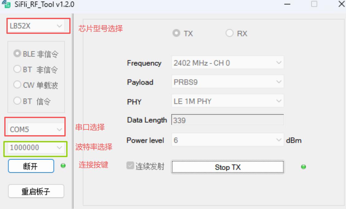
Figure 3-1
Set the channel, PHY type, etc. needed for the test under Frequency, Data Length, payload, and PHY
Click Start TX; when the gray dot to the right of the button turns green, transmission has started successfully, and you can see the corresponding parameters on the tester, as shown in Figure 3-2
To test other channels, PHY types, etc., first click Stop TX, change the settings, and then click Start TX.
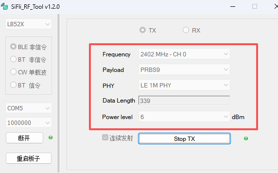
Figure 3-2
3.1.2. BT test method
In the SiFli_RfTool tool, as shown in Figure 3-3:
Select the corresponding chip model (the 52x series is selected in the figure)
Select BT non-signaling and the COM port corresponding to UART1, and set the baud rate to 1000000
Click Connect. Once connected, the status indicator turns green, as shown in Figure 3-3
Note: To switch directly from a BLE non-signaling test to a BT non-signaling test, just click “Stop TX” first and then switch the test mode to BT non-signaling; the serial connection does not need to be re-established.
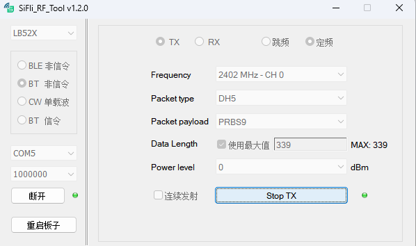
Figure 3-3
Select the Frequency and set the Data Length and Packet Type
Click Start TX; if the gray dot to the right of the button turns green, transmission has started successfully, and you can then see the corresponding metrics on the tester, as shown in Figure 3-4
To test other channels, packet types, etc., first click Stop TX, change the settings, and then click Start TX.
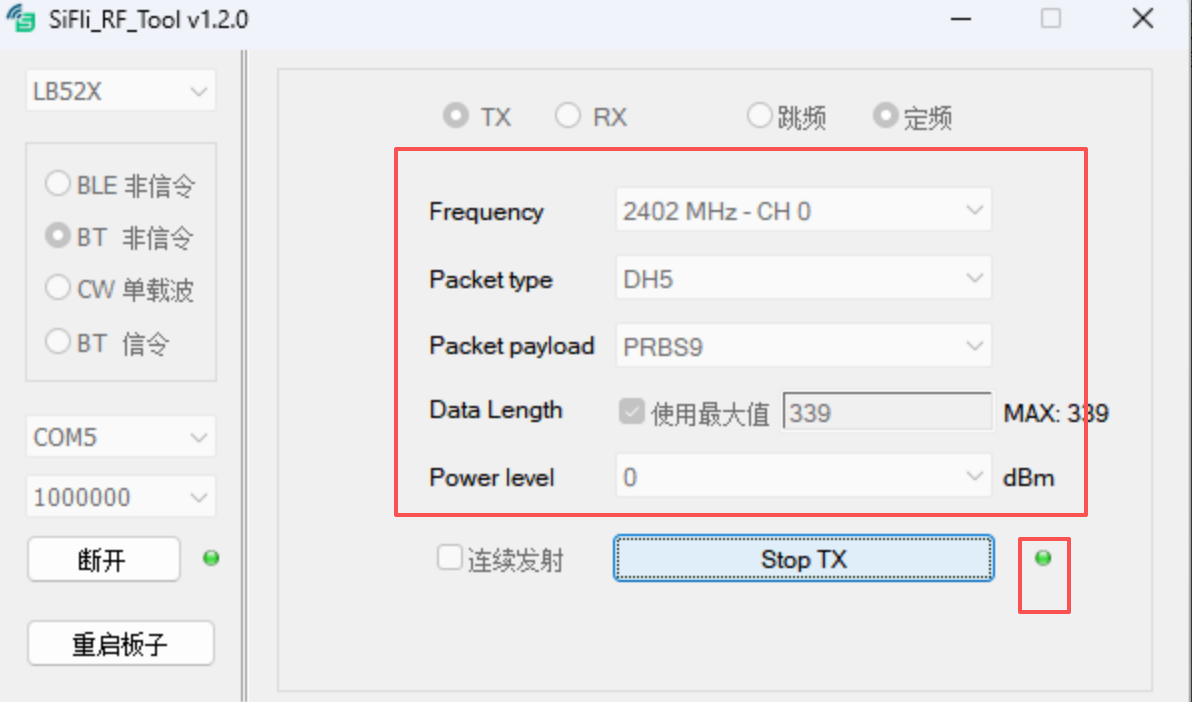
Figure 3-4
3.2. RX Test
After finishing the TX test, you must click Stop to stop the TX test before you can test RX.
Set the Frequency, type, etc.
Click Start RX; if the gray dot to the right of the button turns green, the device has entered the corresponding RX state, as shown in Figure 3-5.
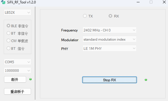
Figure 3-5
To test other channels, first click Stop RX to stop the current RX test state, then change the settings.
3.3. Measured reference data (LB52x HDK)
Below are the measured transmit powers on a SiFli LB52x HDK at different SiFli_RfTool Power level settings, for debugging reference. Actual projects will vary due to differences in board-level matching and PA process; use your own board’s measurements as the reference.
Test condition: Cable loss = 0.3 dB
3.3.1. BLE TX power (Frequency = 2440 MHz)
Level setting |
BLE 1M (dBm) |
BLE 2M (dBm) |
|---|---|---|
13 |
13.46 |
13.44 |
10 |
9.76 |
9.75 |
8 |
7.66 |
7.66 |
6 |
6.57 |
6.58 |
3 |
2.79 |
2.80 |
0 |
0.26 |
0.27 |
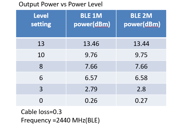
Figure 3-6 Measured BLE TX power curve
3.3.2. Classic BT TX power (Frequency = 2441 MHz)
Level setting |
BR DH1 (dBm) |
EDR 3DH1 (dBm) |
|---|---|---|
13 |
12.52 |
12.47 |
10 |
9.56 |
9.67 |
8 |
7.65 |
— |
6 |
6.64 |
6.46 |
3 |
3.10 |
3.74 |
0 |
0.96 |
0.93 |
EDR does not support the 8 dBm level.
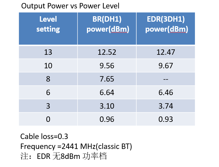
Figure 3-7 Measured Classic BT TX power curve
4. Single-Carrier Signal Test
When switching test items, first click Stop TX, then select the test item to test
Set the corresponding frequency and power level
Click Start TX; when the gray dot to the right of the button turns green, transmission has started successfully, and you can read the corresponding metrics on the tester, as shown in Figure 4-1.
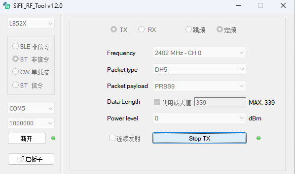
Figure 4-1
To test another channel, first click Stop TX, change the settings, and then click Start TX.
5. Comprehensive Tester Configuration
This chapter covers using the “tool + comprehensive tester” together: the DUT transmits or receives RF signals via SiFli_RfTool, and the tester side is configured for the corresponding mode according to the test direction (DUT transmitting / DUT receiving).
The DUT can be tested either conducted via a coaxial cable or radiated (coupled) over the air; the coupled data is generally lower than the conducted data and requires compensation.
5.1. TX test tester configuration
After completing the SiFli_RfTool-side TX configuration in §3-§4, the DUT is transmitting an RF signal with the configured parameters (using LB56X / BT non-signaling / ch0 / DH1 / PRBS9 / 0 dBm as an example, as in Figure 5-1).
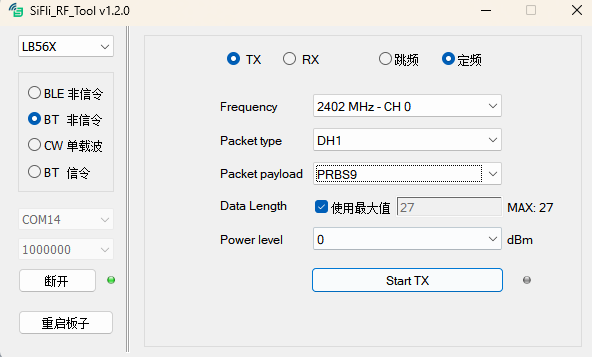
Figure 5-1 Example SiFli_RfTool-side TX configuration
Configure the tester side for non-signaling reception accordingly: on the Multi Evaluation Configuration screen, set the “Scenario” option to “StandAlone (Non Signaling)” and keep the receive parameters — channel, Packet type, Payload, etc. — consistent with the SiFli_RfTool side, as in Figure 5-2.
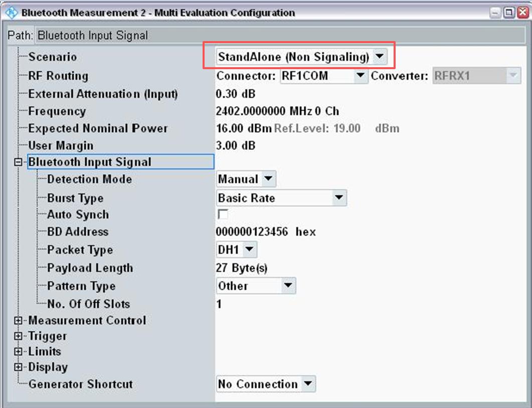
Figure 5-2 Tester Non-Signaling configuration screen
5.2. RX test tester configuration
Testing the DUT’s receive capability works in the opposite direction: the tester transmits a known signal, and the DUT receives it and computes PER/BER. The instrument configuration approach differs between BLE and Classic BT, so they are described separately.
5.2.1. BLE Rx
Switch the CMW500 to the RX Measurement screen; the parameters are shown in Figure 5-3:
Parameter |
Value |
|---|---|
Standard |
LE |
Operating Mode |
Direct Test Mode |
PHY |
1 Mbps |
Channel |
19 |
Frequency |
2440.0 MHz |
Tx Level (CMW) |
-67.00 dBm |
Packet Type |
RF PHY TestRef |
Payload Length |
37 byte(s) |
Pattern Type |
PRBS9 |
Repeat Select |
Single shot (key: this option must be set for correct statistics) |
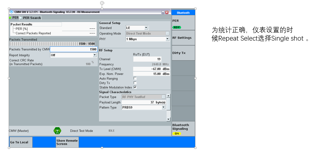
Figure 5-3 CMW500 BLE Rx instrument configuration
Steps:
Click Start RX in SiFli_RfTool; the DUT enters ch19 BLE reception
Set the PER button to ON on the CMW500; the instrument starts transmitting 1500 calibrated packets
Wait about 5 seconds; during this time the SiFli_RfTool tool shows the number of packets received and the RSSI
Click Stop RX in SiFli_RfTool; the tool shows Total rx n packets
Compute PER: PER = (n − 1500) / 1500 × 100% (n is the number of packets the DUT actually received)
Also check the RSSI value in the tool (the theoretical value is about -67 dBm, corresponding to the CMW Tx Level)
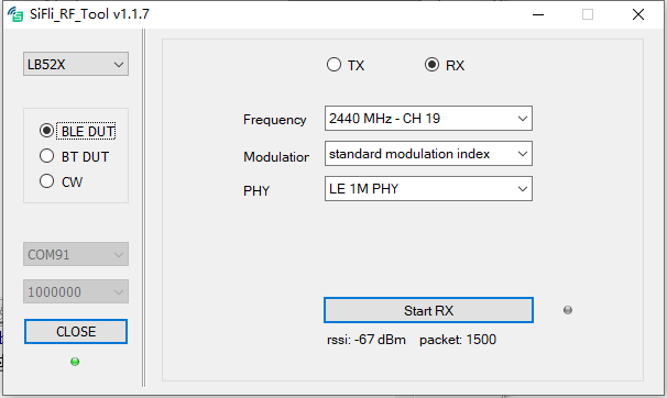
Figure 5-4 BLE Rx test results display (RSSI, packet count)
5.2.2. Classic BT Rx
Classic BT has no standard SIG DTM mode, so the CMW500 transmits by loading a pre-built waveform file through the GPRF Generator. Waveform files include DH1_UAP00.wv and the like; the instrument configuration is shown in Figure 5-5.
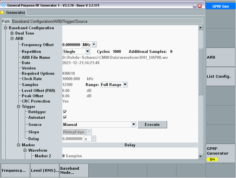
Figure 5-5 GPRF Generator instrument configuration (Classic BT waveform transmission)
Steps:
Select a Classic BT waveform file on the CMW500 (DH1 / 2-DH1 / 3-DH1, etc.)
Click Start RX in SiFli_RfTool; the DUT enters the corresponding BT reception
Toggle the GPRF Generator OFF → ON on the CMW500 to start transmission, and wait about 5 seconds
Click Stop RX in SiFli_RfTool; the tool shows RSSI, packets received, packet errors, packet error rate, bits received, bit errors, and bit error rate (see Figure 5-6)
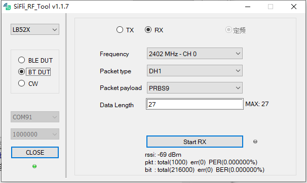
Figure 5-6 Classic BT Rx test results
6. Spectrum Analyzer Configuration
If you don’t have a comprehensive tester, you can use a spectrum analyzer to observe some of the DUT’s metrics. Set the spectrum analyzer’s center frequency to the frequency transmitted by SiFli_RfTool; connect the DUT to the spectrum analyzer via a coaxial cable, and you can see the DUT’s output waveform, as in Figure 6-1.
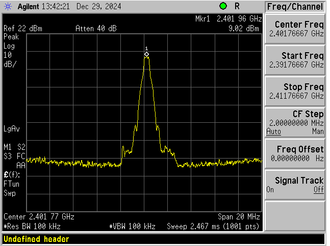
Figure 6-1
7. Troubleshooting
If, during operation, you encounter an unresponsive tool, obviously wrong data, a dropped connection, or similar, reset as follows:
Close the SiFli_RfTool tool
Power off the DUT
Power the DUT back on and wait for it to finish booting
Reopen the SiFli_RfTool tool
Repeat the procedure in the order of this guide’s chapters