
SiFli SDK RF Test Guide
Covers the finsh commands, SDK APIs, parameter values, and event handling for each test mode.
0. Test Mode Overview
Based on test purpose, control method, and application scenario, Bluetooth RF testing falls into three categories: Individual-Item Test, Non-Signaling Test, and Signaling Test. The SDK maps them to different entry points:
Category |
Purpose |
Command Entry Point |
Trigger Source |
|---|---|---|---|
BT Signaling Test |
Bluetooth SIG qualification (QDID), full performance and protocol-conformance evaluation |
|
Over-the-air LMP_test_control from the tester |
BT Non-Signaling Test |
R&D RF debugging, fast production-line RF verification |
|
Local vendor HCI |
BLE Non-Signaling Test (SIG DTM) |
Fast production-line BLE RF testing, SIG-qualified DTM items |
|
Local HCI commands / tester + PC over UART HCI |
Individual-Item Test |
In-depth board-level RF debugging, FCC/CE regulatory pre-testing |
|
Manual, item by item from the PC tool |
Signaling vs. Non-Signaling vs. Individual-Item:
Signaling: the instrument establishes a real Bluetooth link with the DUT and communicates bidirectionally per the standard protocol. Results are authoritative and mandatory for qualification.
Non-Signaling: no Bluetooth connection is established; specific commands drive the RF chip directly into a given state (fixed channel/power/continuous TX or RX) for fast measurement. Used mainly in R&D and on the production line.
Individual-Item: engineers send low-level control commands to the DUT through a PC tool (SiFli_RfTool) to precisely control RF behavior (single carrier, specific modulated signals), analyze each item with a spectrum analyzer / power meter, and perform regulatory pre-testing.
Relationship with BQB qualification: BR/EDR BQB RF testing goes through the BT signaling path, while BLE BQB RF testing goes through SIG DTM (i.e. BLE non-signaling). BT non-signaling is SiFli’s proprietary vendor protocol; it is not part of BQB and is used only for R&D and production. Individual-item testing is also outside BQB and is commonly used for FCC/CE regulatory pre-certification and in-depth board-level tuning.
The SiFli platform provides two kinds of test firmware:
rf_test.bin: the build output of SiFli’s internal, standalone RF-test-only project. Not publicly released; obtain it from an FAE in special cases.
User.bin: any firmware the user builds from this SDK — including the SDK’s bundled examples, the customer’s own product projects, and so on. The SDK integrates RF test functionality into the protocol stack, so this kind of firmware boots into the user application by default and can switch to test mode through finsh commands (
bt_cm dut/bt_cm uart_dut/bt_rftest), with no request to an FAE needed.
This document focuses on User.bin.
1. Build Configuration
1.1 Recommended Base Projects
The following ready-to-use base projects are recommended:
Test Scenario |
Recommended Base Project |
Changes |
|---|---|---|
BT signaling test (BR/EDR DUT mode) |
A BT example that does not disable |
Build as-is; no |
BT non-signaling / individual-item passthrough ( |
Same as above |
No change needed; use as-is |
BLE DTM ( |
Same as above (BT examples include the BLE controller by default) |
No change needed; use as-is |
Tester / PC script driving standard HCI directly (passthrough from boot, no runtime finsh switching) |
No |
1.2 Kconfig Switch Reference
Command / Feature |
Required Kconfig |
Code Location |
|---|---|---|
|
|
|
|
|
|
The UART-switch part inside |
|
|
BT app traces such as |
|
|
BT_FINSHis the master switch for BT-stack debug traces (thebts2_app_demo/bts2_app_menu/bts2_app_genericfamily); do not mistake it for the switch that “enables bt_cm / bt_rftest”.
1.3 Target Device for UART Path Switching
Applies only to bt_cm uart_dut and to custom call sites of uart_ipc_path_change():
# Default is IPC_USE_CONSOLE_DEVICE=y: the console UART runs finsh, and that is the one switched
# To switch a different UART (e.g. point the test port to uart2 in a custom product), set:
CONFIG_IPC_USE_OWN_DEVICE=y
CONFIG_IPC_OWN_DEVICE_NAME="uart2"
2. BT Classic Signaling Test
2.1 Topology
The relationship between the DUT, the tester, and the PC control host:
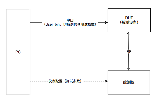
BT signaling test topology
The tester (MT88-series, CMW-series, etc.) acts as the master device over the air and drives the DUT into signaling test mode via LMP commands; the PC controls the tester over UART/GPIB. The DUT itself only needs to set the DUT-enable flag at the protocol-stack layer.
2.2 How to Use
Option |
Call |
|---|---|
FinSH |
|
API |
|
For detailed test procedures, see SF32LB5xx Bluetooth Signaling Test Guide (Chinese).
2.3 Flow
1. The protocol stack starts normally; BLE_POWER_ON_IND has been received
2. The host explicitly enables scan (required):
     bt_interface_set_scan_mode(1, 1);
     // or gap_wr_scan_enb_req(tid, 1, 1);
   gap_enb_dut_mode_req does not auto-enable inquiry/page scan; if the host doesn't, the instrument can't find the DUT.
3. Call gap_enb_dut_mode_req(bts2_task_get_app_task_id()):
   - Sends HCI_Enable_Device_Under_Test_Mode
   - The controller sets the DUT-enable flag and then accepts over-the-air LMP_test_control
4. The console shows "<< enb DUT mode : <step_num>" with no "<< failed to enb DUT mode!" — this means success
5. The instrument (CMW500 in signaling mode) connects over the air:
   inquiry → page → ACL connection → LMP_test_control → enters test mode
6. The instrument runs the test suite
2.4 Complete Code Example
#include "bts2_app_inc.h"  /* includes gap_api.h */

void enter_bt_signaling_dut(void)
{
    gap_enb_dut_mode_req(bts2_task_get_app_task_id());
    /* Wait for the BTS2MU_GAP_ENB_DUT_MODE_CFM event (optional) */
}
In the event callback (inside the BT event handler you registered):
case BTS2MU_GAP_ENB_DUT_MODE_CFM:
{
    BTS2S_GAP_ENB_DUT_MODE_CFM *cfm = (BTS2S_GAP_ENB_DUT_MODE_CFM *)data;
    if (cfm->res == 0)
        LOG_I("DUT mode enabled");
    else
        LOG_E("DUT mode enable failed: %d", cfm->res);
    break;
}
2.5 Notes
Only an “enable” action — it does not make the device transmit on its own. Actual transmission begins only when the instrument triggers it via over-the-air LMP_test_control.
The HCI command channel stays fully functional — after the call you can still issue HCI Reset, Read BD_Addr, and LE DTM commands.
BLE is completely unaffected — the BLE controller keeps working as usual.
The only way to exit is a reset — there is no inverse operation.
Preconditions before calling:
sifli_ble_enable()has completed,BLE_POWER_ON_INDhas arrived, and the current working mode includes BT Classic (dual-mode or BT-only, i.e. the BT stack is loaded).
3. BT Classic Non-Signaling Test
3.1 Topology
Non-signaling testing establishes no Bluetooth link with the DUT; the PC controls the DUT by sending HCI commands over UART, while controlling the tester over UART or GPIB:
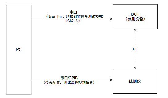
Non-signaling test topology
3.2 How to Use
Option |
Call |
|---|---|
FinSH |
|
API |
|
Header: bf0_ble_common.h
3.3 Opcodes and Parameters
enum bt_test_operation_t {
    BT_TEST_OP_ENTER_TEST,    // Enter non-signaling test mode
    BT_TEST_OP_EXIT_TEST,     // Exit
    BT_TEST_OP_TX_TEST,       // Start transmitting (parameters via tx_para)
    BT_TEST_OP_RX_TEST,       // Start receiving (parameters via rx_para)
    BT_TEST_OP_STOP_TEST,     // Stop the current TX/RX
};

typedef struct {
    uint8_t  channel;     // 0..78, BT channel
    uint8_t  pkt_payload; // 0=PRBS9, 1=11110000, 2=10101010, 3=PRBS15, ...
    uint8_t  pkt_type;    // 0=ID, 1=NULL, 4=DM1, 5=DH5 (common), 14=2-DH5, 15=3-DH5
    uint8_t  pwr_lvl;     // Direct dBm integer (typically 0..13); quantized at runtime to a hardware level supported by the chip PA, see §7.1
    uint16_t pkt_len;     // Payload length; DH5 max is 339
} bt_ns_test_mode_tx_para_t;

typedef struct {
    uint8_t channel;      // 0..78
    uint8_t pkt_type;     // same as above
} bt_ns_test_mode_rx_para_t;
3.4 FinSH Flow Example
msh > bt_rftest enter           # Enter non-signaling test mode
msh > bt_rftest bttx            # ch8, DH5, 339B, PRBS9, pwr=10 (fixed parameters)
... instrument measures TX power and frequency offset (10–30 s) ...
msh > bt_rftest btstop          # Stop TX
msh > bt_rftest btrx            # ch0, DH1 receive
... the instrument transmits from the far end; the DUT computes the packet error rate (PER) ...
msh > bt_rftest btstop
msh > bt_rftest exit            # Exit test mode
The test parameters of the bt_rftest subcommands (channel, packet type, length, power) are fixed inside the SDK. To adjust them, refer to the bt_rftest() implementation in SiFli-SDK/middleware/bluetooth/service/common/bf0_bt_common.c and define your own parameterized subcommands.
3.5 Complete API Usage Example
bt_enter_no_signal_dut_modeis asynchronous. Internally it returnsHL_ERR_NO_ERRORimmediately aftersifli_msg_alloc+memcpy+sifli_msg_send; it takes effect only once theBT_NS_DUT_RSPevent is acknowledged (implementation atbf0_bt_common.c:793). The demo below uses event waits between state transitions to guarantee ordering. If your production code must advance synchronously, signal anrt_event/rt_semfrom theBT_NS_DUT_RSPcallback, or, as a fallback, use an empirical delay (typically 100–200 ms is enough, but not guaranteed).
#include "bf0_ble_common.h"

/* Receive BT_NS_DUT_RSP in the BT event handler and release the waiter (pseudocode) */
static rt_event_t s_bt_ns_evt;       /* created with rt_event_create during module init */
#define EVT_BT_NS_DONE  (1u << 0)

static void on_bt_ns_dut_rsp(bt_ns_test_mode_ctrl_rsp_t *rsp)
{
    /* Dispatch further by rsp->op / rsp->status if needed */
    rt_event_send(s_bt_ns_evt, EVT_BT_NS_DONE);
}

static int wait_bt_ns_done(uint32_t timeout_ms)
{
    rt_uint32_t recved;
    return rt_event_recv(s_bt_ns_evt, EVT_BT_NS_DONE,
                         RT_EVENT_FLAG_OR | RT_EVENT_FLAG_CLEAR,
                         rt_tick_from_millisecond(timeout_ms), &recved);
}

void bt_nonsig_tx_test(uint8_t channel, uint16_t pkt_len, uint8_t pwr_lvl)
{
    bt_ns_test_mode_ctrl_cmd_t cmd;

    /* 1. Enter test mode, wait for ack */
    cmd.op = BT_TEST_OP_ENTER_TEST;
    bt_enter_no_signal_dut_mode(&cmd);
    if (wait_bt_ns_done(500) != RT_EOK) {
        LOG_E("ENTER timeout"); return;
    }

    /* 2. Configure TX parameters and start */
    cmd.op = BT_TEST_OP_TX_TEST;
    cmd.para.tx_para.channel     = channel;
    cmd.para.tx_para.pkt_type    = 5;       /* DH5 */
    cmd.para.tx_para.pkt_len     = pkt_len;
    cmd.para.tx_para.pkt_payload = 0;       /* PRBS9 */
    cmd.para.tx_para.pwr_lvl     = pwr_lvl;
    bt_enter_no_signal_dut_mode(&cmd);
    /* The ack for TX/RX start is also reported via BT_NS_DUT_RSP; production flows should wait too */
}

void bt_nonsig_stop_and_exit(void)
{
    bt_ns_test_mode_ctrl_cmd_t cmd;

    cmd.op = BT_TEST_OP_STOP_TEST;
    bt_enter_no_signal_dut_mode(&cmd);
    wait_bt_ns_done(500);

    cmd.op = BT_TEST_OP_EXIT_TEST;
    bt_enter_no_signal_dut_mode(&cmd);
    wait_bt_ns_done(500);
}
3.6 Receive Results (RX only)
When the BT_NS_DUT_RSP event arrives, the corresponding struct is bt_ns_test_mode_ctrl_rsp_t:
typedef struct {
    enum bt_test_operation_t  op;        // returns cnt on STOP_TEST
    uint8_t                    status;
    bt_ns_test_mode_rsp_para_t para;     // .stop_para.cnt = total packets received
} bt_ns_test_mode_ctrl_rsp_t;
Or use the newer synchronous interface to get PER + RSSI directly:
extern int8_t bt_ns_rx_start(bt_ns_test_new_rx_para_t *rxpara,
bt_ns_test_new_rx_rslt_t *rst,
uint32_t delay_ms);
bt_ns_test_new_rx_para_t para = {
.channel = 8, .pkt_type = 5, .pkt_len = 339, .pkt_payload = 0,
};
bt_ns_test_new_rx_rslt_t rst;
bt_ns_rx_start(¶, &rst, 2000); /* receive for 2s, then stop */
LOG_I("err_bit=%d total_bit=%d err_pkt=%d total_pkt=%d rssi=%d",
rst.err_bit_num, rst.total_bit_num,
rst.err_pkt_num, rst.total_pkt_num, rst.rssi);
3.7 Notes
Use SiFli_RfTool.
You must ENTER before TX/RX, STOP before switching TX/RX, and EXIT last. An incorrect state-machine sequence causes errors.
4. BLE Non-Signaling Test (SIG DTM)
4.1 Topology
All BLE RF testing is done by passing three HCI commands (LE_Transmitter_Test / LE_Receiver_Test / LE_Test_End) over the UART between the DUT and the tester. On the firmware side there is only this one path: switching the UART to HCI passthrough:
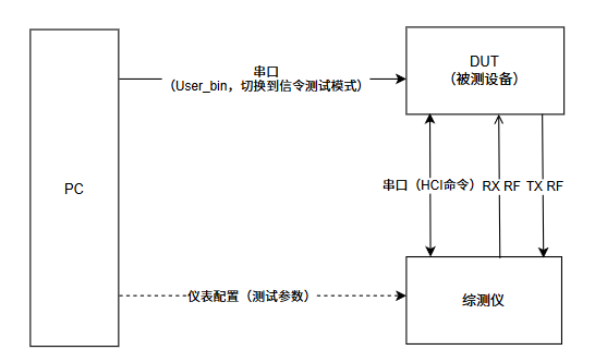
BLE DTM test topology
The DUT and the tester are connected over UART; the tester sends HCI commands to drive the DUT into TX/RX, while the RF test tool on the PC controls the TX/RX of both the DUT and the tester.
4.2 How to Use
Option |
Call |
|---|---|
FinSH |
|
API |
|
Standard HCI (via UART passthrough) |
|
Header: bf0_ble_common.h
4.3 Data Structures
typedef struct {
    uint8_t operation;       // GAPM_LE_TEST_TX_START / RX_START / STOP
    uint8_t channel;         // 0..39 (0=2402MHz, 19=2440MHz, 39=2480MHz)
    uint8_t tx_data_length;  // TX only, 0..255
    uint8_t tx_pkt_payload;  // TX only, gap_pkt_pld_type
    uint8_t phy;             // 1=1M, 2=2M, 3=Coded
    uint8_t modulation_idx;  // RX only, 0=standard, 1=stable
} ble_dut_mode_t;

enum gap_pkt_pld_type {
    GAP_PKT_PLD_PRBS9                = 0,  // default, common on the production line
    GAP_PKT_PLD_REPEATED_11110000    = 1,  // for modulation Δf1/Δf2
    GAP_PKT_PLD_REPEATED_10101010    = 2,  // for carrier frequency offset
    GAP_PKT_PLD_PRBS15               = 3,
    /* also all-0, all-1, F0/0F, AA/55, etc. */
};
4.4 Sending Directly via the API
Both
bt_enter_no_signal_dut_modeandble_enter_dut_modeare asynchronous (implementations atbf0_bt_common.c:769/:793). The two commands are posted to two different task queues, COMMON and GAPM, so you cannot assume they complete serially in call order. Completion events:
ENTER done →
BT_NS_DUT_RSP(op == BT_TEST_OP_ENTER_TEST)TX start done →
BLE_DUT_TX_START_CNFRX start done →
BLE_DUT_RX_START_CNFTest end (STOP) →
BLE_DUT_END_IND(carriesnb_packet_received)Production/product code must wait for the corresponding event before proceeding to the next step. The demo below uses
rt_eventto sequence the whole flow.
#include "bf0_ble_common.h"

static rt_event_t s_dut_evt;
#define EVT_NS_ENTER_DONE   (1u << 0)
#define EVT_BLE_TX_START    (1u << 1)
#define EVT_BLE_END         (1u << 2)

/* Set the corresponding bit in the BT/BLE event handler */
static void on_bt_ns_dut_rsp(bt_ns_test_mode_ctrl_rsp_t *rsp) {
    if (rsp->op == BT_TEST_OP_ENTER_TEST)
        rt_event_send(s_dut_evt, EVT_NS_ENTER_DONE);
}
static void on_ble_dut_tx_cnf(ble_test_tx_start_cnf_t *cnf) {
    rt_event_send(s_dut_evt, EVT_BLE_TX_START);
}
static void on_ble_dut_end(ble_dut_end_ind_t *ind) {
    LOG_I("DTM end, nb_packet_received=%u", ind->nb_packet_received);
    rt_event_send(s_dut_evt, EVT_BLE_END);
}

static int wait_evt(uint32_t bits, uint32_t timeout_ms)
{
    rt_uint32_t recved;
    return rt_event_recv(s_dut_evt, bits,
                         RT_EVENT_FLAG_OR | RT_EVENT_FLAG_CLEAR,
                         rt_tick_from_millisecond(timeout_ms), &recved);
}

/* 1. Enter test mode (BT_TEST_OP_ENTER_TEST is the shared BLE/BT entry) */
bt_ns_test_mode_ctrl_cmd_t enter = { .op = BT_TEST_OP_ENTER_TEST };
bt_enter_no_signal_dut_mode(&enter);
if (wait_evt(EVT_NS_ENTER_DONE, 500) != RT_EOK) {
    LOG_E("ENTER timeout"); return;
}

/* 2. Start TX: ch19 (2440MHz), 37 bytes, PRBS9, 1M PHY */
ble_dut_mode_t tx = {
    .operation       = GAPM_LE_TEST_TX_START,
    .channel         = 19,
    .tx_data_length  = 37,
    .tx_pkt_payload  = GAP_PKT_PLD_PRBS9,
    .phy             = 1,
    .modulation_idx  = 0,
};
ble_enter_dut_mode(&tx);
if (wait_evt(EVT_BLE_TX_START, 500) != RT_EOK) {
    LOG_E("TX start timeout"); return;
}

/* 3. Let the controller transmit continuously for 2s, then stop */
rt_thread_mdelay(2000);
ble_dut_mode_t stop = { .operation = GAPM_LE_TEST_STOP };
ble_enter_dut_mode(&stop);
wait_evt(EVT_BLE_END, 500);   /* receiving BLE_DUT_END_IND means it has stopped */
4.5 Running via FinSH (fixed parameters, ch0)
msh > bt_rftest enter
msh > bt_rftest bletx           # ch0, default 37B PRBS9 1M PHY
... instrument measures ...
msh > bt_rftest btstop
msh > bt_rftest exit
bt_rftest blerx works the same way. After RX completes, nb_packet_received is returned via the BLE_DUT_END_IND event.
4.6 Via HCI Passthrough (driven directly by the tester)
If you use a standard instrument such as the CMW500, skip the API and send HCI directly:
1. msh > bt_cm uart_dut       # switch the UART to HCI passthrough
2. The instrument/script then sends standard HCI commands over this UART:

   01 1E 20 03 13 25 00       LE_Transmitter_Test    ch19, 37B, PRBS9
   01 33 20 03 13 01 00       LE_Receiver_Test v2    ch19, 1M PHY, modulation=standard
   01 1F 20 00                LE_Test_End → returns packet_count

3. Exit: reset the chip, or call `uart_ipc_path_revert()` to switch back in software (see §11.5)
4.7 Event Callbacks
case BLE_DUT_TX_START_CNF: {
    ble_test_tx_start_cnf_t *cnf = (ble_test_tx_start_cnf_t *)data;
    LOG_I("TX start, status=%d", cnf->status);
    break;
}
case BLE_DUT_RX_START_CNF: {
    ble_test_rx_start_cnf_t *cnf = (ble_test_rx_start_cnf_t *)data;
    LOG_I("RX start, status=%d", cnf->status);
    break;
}
case BLE_DUT_END_IND: {
    ble_dut_end_ind_t *ind = (ble_dut_end_ind_t *)data;
    LOG_I("Test end, packet_count=%d", ind->nb_packet_received);
    /* packet_count is always 0 in TX mode; this is per-spec behavior */
    break;
}
4.8 Notes
No
gap_enb_dut_mode_reqneeded: BLE DTM is non-signaling and does not require setting the BT Classic DUT-enable flag.packet_count is always 0 for TX tests (per spec); it is meaningful only for RX.
BLE and BT Classic share the radio and cannot run in parallel.
5. Individual-Item Test (SiFli_RfTool)
For board-level RF tuning during development and for regulatory pre-testing. Engineers use the PC-side SiFli_RfTool to send low-level control commands to the DUT over UART, precisely controlling RF behavior (single carrier, specific modulated signals, fixed channel/power) and measuring each item with instruments such as a spectrum analyzer and power meter.
Tool location: tools/SiFli_RfTool/SiFli_RfTool.exe, runs directly on Windows.
For detailed individual-item test steps, see SF32LB5xx Bluetooth Individual-Item Test Guide (Chinese).
5.1 Entry Points
Option |
Call |
|---|---|
FinSH |
|
API |
Same as Chapter 2 ( |
After the firmware completes the switch, SiFli_RfTool sends low-level HCI / vendor commands over the UART to control each item. The firmware itself needs no extra logic — it only has to release the UART path.
5.2 Usage
On the DUT, run bt_cm uart_dut → open SiFli_RfTool on the PC → select the serial port and baud rate → send commands item by item from the tool’s UI. The serial commands can also be triggered with SiFli_Trace or another general-purpose serial tool (common in signaling test mode).
6. RF Debug UART and Baud Rate
Default RF debug UART and pin mapping for each chip (default baud rate 1000000, i.e. 1 Mbps):
Chip |
Interface Type |
Pins |
UART Channel (TX / RX) |
Notes |
|---|---|---|---|---|
SF32LB551 |
RF debug UART |
PA49, PA51 |
UART1: TX(PA49) / RX(PA51) |
|
SF32LB551 |
Single-carrier test |
PB45, PB46 |
UART3: TX(PB45) / RX(PB46) |
|
SF32LB555 |
RF debug UART |
PA17, PA19 |
UART1: TX(PA17) / RX(PA19) |
|
SF32LB555 |
Single-carrier signal port |
PB45, PB46 |
UART3: TX(PB45) / RX(PB46) |
|
SF32LB561 / SF32LB563 |
RF debug UART |
PA17, PA18 |
UART1: TX(PA17) / RX(PA18) |
|
SF32LB567 |
RF debug UART |
PA34, PA30 |
UART1: TX(PA34) / RX(PA30) |
|
SF32LB52x |
RF debug UART |
PA19, PA18 |
UART1: TX(PA19) / RX(PA18) |
Shares pins with the firmware download port |
SF32LB58x |
RF debug UART |
PA31, PA32 |
UART1: TX(PA31) / RX(PA32) |
|
SF32LB57x |
RF debug UART |
PA19, PA18 |
UART1: TX(PA19) / RX(PA18) |
For historical reasons, on the SF32LB55X series the single-carrier test must use UART3. On all other chips, all RF testing uses UART1.
The tester (MT88-series, CMW-series) must match this baud rate in its HCI-over-UART configuration (default 1 Mbps). If the link is unstable, drop to 921600 / 460800 / 115200 and lower the tester side accordingly.
7. RF Power Levels and Configuration
7.1 Supported Power Levels
The power levels the chip PA can output stably (other dBm values are internally quantized to the nearest level):
Level |
Notes |
|---|---|
0 dBm |
|
3 dBm |
|
6 dBm |
|
9 dBm |
|
13 dBm |
|
19 dBm |
Supported only for BR/EDR and BLE |
The software API (
pwr_lvl, KconfigBT_TX_POWER_VAL_*) accepts any integer dBm — not a level index; the controller quantizes it to the nearest hardware level at runtime.
8. HCI Command Quick Reference
A quick reference of the HCI commands commonly used for BT/BLE RF testing:
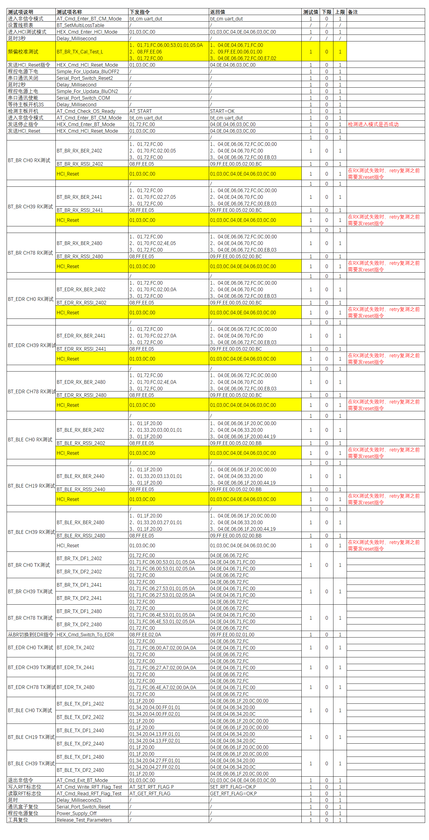
HCI command set
Some key opcodes:
Command |
OGF/OCF |
Full opcode (LE) |
|---|---|---|
HCI Reset |
0x03 / 0x0003 |
|
HCI Read BD_Addr |
0x04 / 0x0009 |
|
HCI Enable Device Under Test Mode |
0x06 / 0x0003 |
|
LE Receiver Test v2 |
0x08 / 0x0033 |
|
LE Transmitter Test |
0x08 / 0x001E |
|
LE Test End |
0x08 / 0x001F |
|
For more detailed command parameters and response fields, refer to the Bluetooth Core Specification, Volume 4 Part E (HCI). SiFli’s proprietary vendor commands (used for BT non-signaling testing) are not part of the SIG standard; they are wrapped inside the APIs in Chapter 3, so there is no need to assemble the bytes manually.
9. The Three Test Modes Cannot Run in Parallel
The LCPU has only one RF front end, so it can be in only one test mode at any time:
Normal running state ──[gap_enb_dut_mode_req]──────────────────→ BT signaling DUT-ready state
                     ──[bt_enter_no_signal_dut_mode(ENTER+TX)]──→ BT non-signaling test state
                     ──[ble_enter_dut_mode(TX_START)]──────────→ BLE DTM test state
Switching rules:
Before entering any test mode, if you were in another test mode, you must EXIT cleanly first
BT signaling DUT and BT non-signaling are mutually exclusive; EXIT before switching
BLE DTM and BT non-signaling are mutually exclusive (they share the ENTER state); EXIT and then ENTER before switching
10. Adding a Custom Test Entry in Your Product
If you want to add the ability to “trigger RF testing via a proprietary protocol command” in your own product (e.g. a production-line station sends one command and the module enters DUT), refer to the two templates below.
Template A: set the BT Classic DUT-enable flag and leave the UART untouched. Exit by reset.
void product_enter_bt_signaling_dut(void)
{
    gap_enb_dut_mode_req(bts2_task_get_app_task_id());
    /* The application UART keeps working; the instrument connects over the air to trigger the test */
}
Template B: switch the application UART to HCI H4 passthrough for the CMW500.
After this, the calling thread must not return to its main loop and access that UART, otherwise the next rt_device_read(NULL) will assert. You must release the UART and permanently suspend the current thread:
extern void uart_ipc_path_change(void);

void product_enter_hci_passthrough(void)
{
    /* 1. Send something like an ACK back to the host, then wait for TX to drain */
    rt_thread_mdelay(50);

    /* 2. Release the application UART: stop the RX thread, unbind rx_indicate, close the device */
    my_app_release_uart();

    /* 3. The SDK takes over the UART and starts the fwd2mb / fwd2uart forwarding threads */
    uart_ipc_path_change();

    /* 4. Permanently suspend the current thread so it can't return and access the closed UART */
    rt_thread_suspend(rt_thread_self());
    rt_schedule();
    /* never returns */
}
What my_app_release_uart() must do:
Signal your RX thread that it should exit (a flag or semaphore)
rt_device_set_rx_indicate(dev, RT_NULL)rt_device_close(dev)
Your send-side APIs (the product’s own xxx_uart_send) must include a NULL check after release; otherwise later event reporting will trigger a null-pointer dereference.
10.1 Where to Hook the Command Handler
The hook point depends on your product’s command system:
Command System |
How to Hook |
|---|---|
Standard finsh / MSH |
Export directly with |
Custom text protocol (AT, proprietary ASCII, etc.) |
Add it to the protocol parser’s command dispatch table; the handler runs on the protocol-parsing thread |
Binary proprietary protocol |
Add it to the opcode dispatch switch; the handler runs on the protocol-parsing thread |
Remote trigger over BLE/SPP |
Call it from the GATT write callback or the SPP data callback |
Mind the handler’s thread context: Template B’s rt_thread_suspend(rt_thread_self()) suspends the thread on which uart_ipc_path_change() is called. If your handler runs on the protocol-parsing thread (the typical case), that thread is the one suspended, and none of its subsequent processing runs afterward — this is expected behavior.
If you don’t want the whole protocol-processing thread frozen, you can spawn a temporary one-shot thread dedicated to Template B’s logic and suspend that thread instead; but this gains little, because once the UART is switched the protocol-parsing thread has nothing left to do anyway (the UART no longer belongs to it), so it makes no difference which thread is suspended.
10.2 Calling Preconditions
Both Template A and B require the BT stack to be ready:
sifli_ble_enable()has been called and theBLE_POWER_ON_INDevent has arrivedWhen the current working mode includes BT Classic (dual-mode or BT-only),
bt_interface_set_scan_mode(1, 1)has taken effect
If these steps complete asynchronously in your product’s power-up flow, the handler must guard against it:
extern app_env_t *app_get_env(void);   /* however your product tracks stack state */

static void product_enter_dut(void)
{
    if (!app_get_env()->is_power_on)
    {
        /* The stack isn't up yet; calling now would go nowhere */
        respond_error("stack not ready");
        return;
    }
    gap_enb_dut_mode_req(bts2_task_get_app_task_id());
    respond_ok();
}
11. Data-Path Changes After HCI Passthrough
After Template B calls uart_ipc_path_change(), be aware of what changes on that UART, or you’ll hit pitfalls:
11.1 What Happens
Before Switch |
After Switch |
|---|---|
RX data is consumed by your protocol-parsing thread |
RX data is read by the SDK’s |
TX is done by your protocol code via |
TX is done by the SDK’s |
|
|
Log output goes through ulog → the console UART (possibly this one) |
If the console UART is the one switched, |
The UART carries a text / proprietary protocol |
The UART carries an HCI H4 binary stream |
11.2 What to Avoid After Switching
Don’t call any of your previous
xxx_uart_send/xxx_uart_send_str: even with a NULL check that prevents a crash, if these bytes are mistakenly written to the UART the SDK will treat them as an HCI command and forward them to the LCPU. After parsing them as an H4 frame, the LCPU gets an invalid opcode or invalid length. At best it returnsUnknown HCI Command (0x01)/Invalid HCI Parameters (0x12); at worst, the byte stream of a subsequent valid HCI command is truncated by the bad frame’sparam_len, causing command loss or misaligned responsesDon’t trigger any log output to this UART:
log_pause(true)has paused the ulog framework, but if you bypass ulog and callrt_kprintfdirectly, those bytes leak into the HCI stream and corrupt the hostDon’t report any more events on this UART: periodic output such as disconnect/connect events and heartbeats must be stopped
11.3 What You Can Do After Switching
Receive HCI commands from this UART (sent by the instrument/PC script; opcode encoding matches the table in §8, with
OGF/OCFcombined into a 16-bit value):Standard BLE DTM:
HCI_LE_Transmitter_Test(0x08/0x001E),HCI_LE_Receiver_Test v2(0x08/0x0033),HCI_LE_Test_End(0x08/0x001F)General HCI:
HCI_Reset(0x03/0x0003),HCI_Read_BD_Addr(0x04/0x0009), etc.SiFli proprietary BT non-signaling vendor commands: see Chapter 3
Observe HCI events on this UART: each command should return a Command Complete event (type
0x04, event code0x0E)
11.4 H4 Frame Format Quick Reference
Send (host → controller):
| type | opcode_lo | opcode_hi | param_len | params... |
| 0x01 |  XX       |    XX     |    XX     |   ....    |
Receive (controller → host):
| type | event_code | param_len | params... |
| 0x04 |    0x0E    |    XX     |   ....    |  ← Command Complete
The opcode is little-endian 16-bit; e.g. LE_Transmitter_Test is 0x201E, serialized as 1E 20.
11.5 Switching Back to the Application State
The SDK provides a software inverse operation uart_ipc_path_revert() (implementation at bluetooth_config.c:1634) to restore without a reset:
extern void uart_ipc_path_revert(void);

uart_ipc_path_revert();
/* After this:
   - rx_indicate / open_flag are restored to their pre-switch values
   - log_pause(false) restores ulog output
   - trans_en=0 tells the fwd2mb / fwd2uart forwarding threads to stop moving data
   - the LCPU low-power activity lock is released
*/
Limitations of the software switch-back:
uart_ipc_path_revertdoes not destroy thef2mb_th/f2uart_thforwarding threads; they keep existing and merely stop moving data becausetrans_en=0It does not call
rt_device_close, so the UART device’s ref_cnt is not restoredIf later application code needs to re-acquire the UART (
rt_device_open/ setting a newrx_indicate), make sure its re-entry logic doesn’t assume “the device was not previously opened”
If your production flow requires “fully returning to the application state after RF testing, leaving no SDK background threads”, a reset path is still recommended; uart_ipc_path_revert is best for repeated switching during debugging/development, avoiding a hardware restart each time.
12. Verifying Your Implementation
Verify in the following order.
12.1 The Command Itself Works
Send the command → check whether the console shows the line printed by the BTS2MU_GAP_ENB_DUT_MODE_CFM handler (using BT signaling DUT as an example):
D/btapp_ge: << enb DUT mode : <step_num>
Implementation: bts2_app_generic.c:1738-1752. <step_num> is a step counter whose exact value depends on the implementation and should not be checked as a fixed value. The criterion is: this log appears and is not accompanied by << failed to enb DUT mode! (the latter is triggered by res != BTS2_SUCC).
If neither line appears, the command never reached the LCPU; trace back the BLE_POWER_ON_IND timing, whether the stack started, whether the handler actually ran, and whether CONFIG_BT_FINSH=y is enabled (otherwise this trace won’t appear).
12.2 Confirming Scan Mode
gap_enb_dut_mode_req does not auto-enable scan; whether the instrument can discover the DUT depends on whether the host previously called bt_interface_set_scan_mode(1, 1) or gap_wr_scan_enb_req(tid, 1, 1). Read the current cached value to confirm:
uint8_t scan = bt_interface_get_current_scan_mode();
LOG_I("scan mode = %d", scan);
/* 0 = none; 1 = inquiry only; 2 = page only; 3 = both inquiry+page */
If the host set scan_mode=3 before sending the DUT command, you should read 3 here; otherwise it returns the actual scan state. Reading anything other than 3 means your init flow didn’t enable scan — add bt_interface_set_scan_mode(1, 1) before sending the DUT command.
12.3 Verifying the HCI Passthrough Link (Template B)
After switching the UART, use a PC serial tool (in hex mode) to send HCI Reset:
TX: 01 03 0C 00
RX: 04 0E 04 XX 03 0C 00
Getting a response means the HCI passthrough link is up. XX is the num_hci_cmd_packets field (any value); what matters is the leading 04 0E (Command Complete event) and the trailing 03 0C 00 (corresponding to the HCI_Reset opcode + status 0).
Then send LE Transmitter Test:
TX: 01 1E 20 03 13 25 00      LE_Transmitter_Test ch19, 37B, PRBS9
RX: 04 0E 04 XX 1E 20 00       Command Complete, status 0
The controller starts transmitting continuously on ch19; a spectrum analyzer or CMW500 will now show a signal at 2440 MHz.
12.4 Full RF Metric Verification
Connect a CMW500 (or a comparable instrument such as the R&S CBT or Anritsu MT8852B), run the test suite per the SIG DTM standard, and check whether TX power, frequency offset, and PER are within spec. This step is done on the instrument and requires no code from you.
13. Complete Integration Example
Assume you already have an RT-Thread + SiFli SDK project running its own command system (this section is general, not limited to finsh / a custom protocol). Below is a complete set of steps to integrate a “DUT test command”, using Template A (signaling DUT, no UART switch) as the example.
Step 1: Add configuration to proj.conf
CONFIG_BT_FINSH=y
CONFIG_RT_USING_FINSH=y
Step 2: Add a handler in your command-handling code
#include "bts2_app_inc.h"     /* includes gap_api.h */

static int s_dut_armed = 0;

static void cmd_dut_handler(...)
{
    if (!app_stack_ready())
    {
        respond_error("stack not ready");
        return;
    }

    if (s_dut_armed)
    {
        respond_error("already in DUT");
        return;
    }

    gap_enb_dut_mode_req(bts2_task_get_app_task_id());
    s_dut_armed = 1;
    respond_ok();
}
The s_dut_armed flag prevents repeated calls that would confuse the LCPU state.
Step 3: Hook into command dispatch
Depending on your project’s command system:
finsh:
MSH_CMD_EXPORT(cmd_dut_handler, enter BT signaling DUT mode)Command-table dispatch: add a line
{ "DUT", cmd_dut_handler }Remote trigger over BLE/SPP: call it when a specific opcode is received
Step 4: Rebuild, reflash, and power up
Confirm the power-up flow completes and an application command (any existing command) responds normally, proving the stack and command system are ready.
Step 5: Send the DUT command
After receiving the OK response, immediately check the console log; you should see << enb DUT mode : <step_num> as described in §12.1, with no accompanying << failed to enb DUT mode!.
Step 6: Connect the instrument and run the test
Configure the CMW500 with the Bluetooth Signaling test module, set DUT Connection to BD Address (read it with Read_BD_Addr and fill it in), and start the test suite. The instrument automatically runs inquiry → page → ACL → LMP_test_control and executes the full BQB test matrix.
Step 7: Exit the test
Just reset the chip.
For Template B (HCI passthrough): in Step 1 also add the IPC UART configuration (see Chapter 1); in Step 2 replace the handler body with the Template B code plus an implementation of my_app_release_uart(); after Step 5 switch to the PC-script verification in §12.3; in Step 6 connect the instrument directly to the switched-away UART (no BD Address flow needed — the instrument sends HCI commands directly).
14. Troubleshooting
Symptom |
Cause |
Fix |
|---|---|---|
Calling |
The stack isn’t up |
Wait for |
The |
The LCPU didn’t receive the command |
Check whether mailbox / sifli_msg_send is working |
After |
The state machine is out of order |
Reset and run through the flow again |
No HCI response after |
|
Check |
The controller receives no commands after |
The UART is still held by the original stack thread |
Close the device and unbind rx_indicate before switching |
The RX thread asserts |
The calling thread returned to its main loop and accessed the device again |
The caller must permanently suspend with |
HCI commands occasionally drop bytes |
1 Mbps is unstable on some USB-UART adapters |
Drop to 921600 or 460800 |
packet_count reads 0 after a BLE TX test |
That’s how the spec works |
packet_count is meaningful only for RX tests |
TX power is off during BT non-signaling tests |
|
Enter the target dBm value directly; the controller quantizes it at runtime to a hardware level supported by the PA (see §7.1); default is 10 |
15. Key Source Locations
Module |
File |
|---|---|
BT signaling DUT API |
|
BT non-signaling / BLE DTM API |
|
|
|
|
|
|
|
HCI passthrough threads / IPC mailbox |
Same file: |
16. Reference Examples and Documents
Base examples for BT signaling / non-signaling / individual-item / DTM testing: any BT example under
example/bt/, such asexample/bt/spp/Boot-time HCI passthrough example (driven directly by a tester/PC script):
example/bt/HCI_over_uart/The SiFli_RfTool tool itself:
tools/SiFli_RfTool/SiFli_RfTool.exe(bundled with the SDK, no installation)SiFli_RfTool user manual: SiFli_RfTool_UM
Individual-item testing and instrument operation guide: SF32LB5xx Bluetooth Individual-Item Test Guide (Chinese)