
SDADC Example
Source code path: example/rt_device/adc/sdadc
Overview
Under the RT-Thread operating system, the SDADC peripheral is virtualized as an
rt_device. It is accessed through the standard RT ADC framework (rt_device_find+rt_adc_enable+rt_adc_read) via the"sdadc"device to perform voltage sampling.This example demonstrates the complete chain of multi-channel scanning + timer trigger + interrupt notification (event-driven): GPTIM3 periodically triggers a scan round → the hardware refreshes each channel’s result into its corresponding output register → the conversion-complete interrupt fires → the driver callback
rx_indicatewakes up the application → the application reads the latest voltage of each channel one by one.
Supported Platforms
The example can run on the following development board.
sf32lb58 HDK
Note: The SDADC IP is only available on SF32LB55X and SF32LB58X chips. This example was debugged on the 58 series.
Sampling Modes Supported by the SDADC Driver
The SDADC driver supports two orthogonal dimensions, which are combined through Kconfig:
Dimension |
Option |
Description |
|---|---|---|
Channel count |
|
Off: single channel; On: multi-channel scanning (configure once, sample multiple channels separately) |
Trigger source |
|
Off: software trigger (actively starts a conversion on read); On: GPTIM3 timer trigger, with conversion-complete interrupt enabled |
All four combinations are available: single channel + software trigger, single channel + timer trigger, multi-channel + software trigger, multi-channel + timer trigger. This example uses multi-channel + timer trigger + interrupt notification by default.
Hardware Connection
Mapping between SDADC channels and pins (driver channel numbers 1~4):
Chip |
CH1 |
CH2 |
CH3 |
CH4 |
|---|---|---|---|---|
SF32LB55X |
PB_23 |
PB_24 |
PB_25 |
PB_26 |
SF32LB58X |
PB_40 |
PB_41 |
PB_42 |
PB_43 |
Connect the target SDADC pin to an external voltage source (0 ~ reference voltage). GND must share a common ground with the development board. A channel with no signal connected will read floating noise, which is normal.
Usage
Build and Flash
This example uses the SDADC RT driver. Make sure
rtconfig.hcontains the following macros:
#define BSP_USING_SDADC 1
#define RT_USING_ADC 1
Only when these macros are present will the sifli_sdadc_init function register the "sdadc" device through
rt_hw_adc_register, allowing subsequent rt_device_find and rt_adc_read calls to succeed.
The
proj.confof this example already enables the required configuration:
CONFIG_BSP_USING_SDADC=y
CONFIG_BSP_SDADC_USE_TIMER_TRIGGER=y       # Timer trigger + conversion-complete interrupt
CONFIG_BSP_SDADC_TIMER_PERIOD_MS=1000      # Timer period (ms)
CONFIG_BSP_SDADC_SUPPORT_MULTI_CH_SAMPLING=y   # Multi-channel scanning
For manual configuration, use
menuconfig(replaceyour_boardwith the board name you actually use):
sdk.py menuconfig --board=your_board
Select the SDADC, multi-channel sampling, timer trigger and other options as shown, then save and exit.
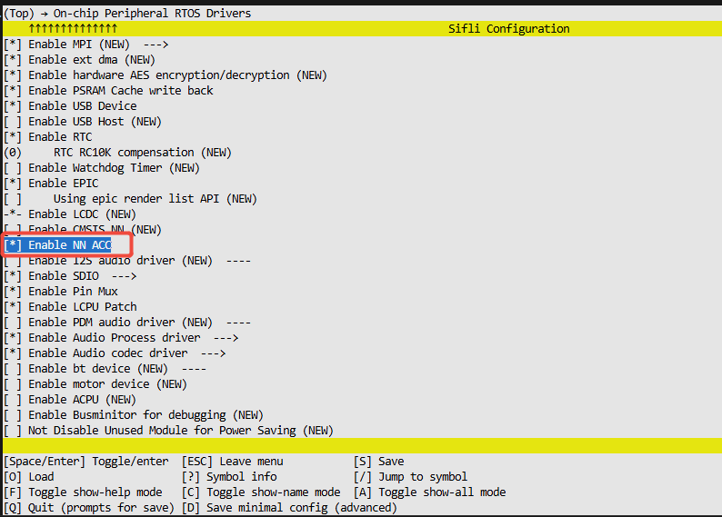
Switch to the example project directory and run scons to build (using ec-lb587 as an example):
scons --board=ec-lb587_hcpu -j8
Run
build_ec-lb587_hcpu\uart_download.batand follow the prompts to select the serial port for download.
Example Output:
Each time a conversion-complete interrupt notification is received (approximately equal to the timer period),
a set of 4-channel voltage values is printed (in 0.1mV units; ch1: 6580 (658.0 mV) means 658.0mV):
======== SDADC Multi-Channel (IRQ-driven) Example ========
I/sdadc: SDADC ch1 enabled
I/sdadc: SDADC ch2 enabled
I/sdadc: SDADC ch3 enabled
I/sdadc: SDADC ch4 enabled
I/sdadc: SDADC multi-channel + timer trigger + interrupt, 4 channels
msh />
I/sdadc: ch1: 7025 (702.5 mV)
I/sdadc: ch2: 4761 (476.1 mV)
I/sdadc: ch3: 6618 (661.8 mV)
I/sdadc: ch4: 6391 (639.1 mV)
If
SDADC conversion-complete notification timeoutis printed continuously, it means no interrupt notification was received. Check whether the timer trigger and the SDADC interrupt are working properly.
Example Flow
Configure pinmux for each channel to be sampled (
HAL_PIN_Set+HAL_PIN_Selectto switch to the SDADC analog function)rt_device_find("sdadc")to find the SDADC deviceFor each channel,
rt_adc_enable(dev, channel)to enable the corresponding sampling slot.Initialize the semaphore and register the conversion-complete callback with
rt_device_set_rx_indicateIn the main loop,
rt_sem_takewaits to be woken by the interrupt notification, thenrt_adc_readreads the voltage of each channel
Switching to Other Sampling Modes
Single channel: In
proj.conf, removeCONFIG_BSP_SDADC_SUPPORT_MULTI_CH_SAMPLING=y, and changeg_sdadc_channelsinmain.cto a single channel (e.g.{3}).Software trigger: Remove
CONFIG_BSP_SDADC_USE_TIMER_TRIGGER=y. In this case there is no timer or conversion-complete interrupt; eachrt_adc_readactively starts a conversion (blocking until complete). The application side should revert to thert_thread_mdelay+rt_adc_readpolling approach and no longer wait forrx_indicate.Timer without interrupt notification: Keep the timer trigger, but do not call
rt_device_set_rx_indicate. The main loop can simply poll withrt_thread_mdelay+rt_adc_read.
Troubleshooting
find sdadc failed—BSP_USING_SDADCis not enabled, the SDADC driver is not compiled, and the"sdadc"device is not registered.rt_adc_enable chN failed— the channel number is out of range (valid 1~4), or SDADC hardware initialization failed.SDADC conversion-complete notification timeout— no interrupt notification received: confirm thatBSP_SDADC_USE_TIMER_TRIGGERis enabled (the driver enables both the timer trigger and the conversion-complete interrupt), and check whether GPTIM3 is running properly.A channel always reads 0 or abnormal values —
Check whether the channel pin has a signal connected and shares a common ground with the board;
Check whether the
HAL_PIN_Selectfunction selection value for the pad is correct (this example uniformly uses10; if a channel does not match, refer to the pin configuration table to confirm);In multi-channel mode, confirm that the channel has been
rt_adc_enabled (a slot that has not been enabled will not be scanned).Check whether the chip’s SDADC has been factory-calibrated. Check whether the
Get SDADC configure fail, use default calibrationlog appears in the boot log.
Revision History
Version |
Date |
Release Notes |
|---|---|---|
0.0.1 |
07/2026 |
Initial version |